
by NATHAN OKUN (Revised 5/3/98)
COLUMN HEADER DEFINITIONS
NOTE: If two numbers are separated by a dash (-), they represent a range of values, with the larger value usually for the thinnest plates of the armor type.
MATERIAL - Name of armor/construction material in common use at the time by the people using it. If "AVE." is in name, then the material is the average of two or more materials of the same kind made at the same time by more than one manufacturer for the same purpose, but for which separate data either is not known or is not important since the material is used interchangeably and which manufacturer's plate is used is not known.
COUNTRY - Nation making this particular kind of armor/construction material.
COMPANY - Manufacturer of the armor/construction material.
TIME FRAME - Years that armor was manufactured or used aboard ship, as relevant.
TENSILE* - TENSILE STRENGTH. Test sample's minimum slow stretching force per unit original cross-sectional area needed to tear the sample into two separate parts, in pounds/square inch. The higher that this is, the stronger the metal is against slowly-increasing, non-impact loads.
YIELD* - YIELD STRENGTH. Test sample's minimum slow stretching force per unit original cross-sectional area needed to make the sample permanently lengthen by 2%, in pounds/ square inch. The higher that this is, the stronger the metal is against slowly-increasing, non-impact loads, but only against impact loads if the tensile strength is going up by the same percentage.
Y/T* - YIELD STRENGTH TO TENSILE STRENGTH RATIO. The closer to "1" that this value is, the less "give" the material has and more brittle the material will be if all else is equal.
% EL* - PERCENT ELONGATION. Percent by which the sample's length had increased just as it snapped in two. The larger the value, the more ductile the sample.
% RA* - PERCENT REDUCTION IN AREA. Percent of the sample's original cross-sectional area by which the narrowest point of the sample had shrunk just as it snapped in two. The larger the value, the more ductile the sample.
BRINELL - BRINELL HARDNESS NUMBER. Developed in the early 20th Century in Sweden as a measure of the resistance of a material to local deformation under a near-point stress, here a tiny tungsten (wolfram)-carbide ball under a 3,000 kg (6,614.4 lb) load (other versions of this scale exist, but this covers the largest range for hard materials). A formula for the size of the pit formed gives the Brinell Number, with wrought iron being about 100 (actually, 105 is the average) and circa 794 being as hard as the hardest pure cementite (actually, as the hardness goes above 650, the tiny ball begins to flatten out and the values give a greater difference than is actually there, while above 739 the tiny ball flattens out so badly that it cannot be used). This is only one of several competing hardness scales, but one of the most widely used, so I use it in place of such possibly more accurate hardness scales Rockwell "B" and "C" (58 RB = 105 Brinell, 22.5 RC = 100 RB = 240 Brinell (usual cross-over point where RC replaces RB for harder materials), 65 RC = 739 Brinell) or Vickers Pyramidal (97.5 RB = 20 RC = 238 Vickers = 226 Brinell (minimum RC and Vickers), 251 Vickers = 240 Brinell, and 832 Vickers = 739 Brinell). Though Brinell testing is not usually used here, a hardness of 66 RC is roughly 757 Brinell, 67 RC is roughly 775, and 68 RC (highest RC used) is roughly 794--these Brinell values would need a test ball harder than tungsten carbide to reach (diamond?). A slash (/) means "face maximum/back average" for face-hardened armors. NOTE: The hardness values given here are typical for the given plate type, usually with a range of about 20-30 up and down for a hard face and 5-10 up and down for the rest, centered on the given value.
USAGE - Portions of the ship that the material is used on and why, including restrictions to thickness used, if any.
*BACK LAYER values of these quantities usually given for face-hardened armors, except for COMPOUND ARMOR, where the numbers are estimates of the surface of the hard steel face layer (the back layer is regular homogeneous WROUGHT IRON ARMOR).
ARMOR - Metal plate used primarily to keep enemy weapon effects outside of an area of a target, sometimes also being used as part of the construction material for building that portion of the target, but in many cases just an additional layer of specially-formulated resistive material placed on top of the separate construction material. Also called "protective plating" and sometimes only designed to protect against secondary effects such as blast or fragmentation, while at other times designed to resist direct hits by the enemy weapons expected to be used against it under specified conditions (gun range and Target Angle for gun projectiles or aircraft altitude for bombs).
ARMOR-PIERCING (AP) - Projectiles designed to penetrate heavy armor (over circa half-caliber thickness) under a specified set of conditions with minimal damage, so that the projectiles will cause the maximum expected damage to the target, such as exploding as designed if it has an explosive filler. The maximum impact obliquity and plate thickness allowing this gradually increased as time went on and metallurgical expertise increased. Explosive filler, if used at all, was very small (4% or less in WWI and 3% or less in WWII) and a base fuze was used, with or without a time delay element. Naval designs usually employed an AP cap after circa 1898 to allow them to remain unshattered against contemporary face-hardened armor.
BALLISTIC LIMIT - Minimum striking velocity of a specific projectile against a specific plate under a given set of conditions (impact obliquity, etc.) that will allow the projectile to barely defeat the plate using its kinetic energy (not meaningful for projectiles that rely primarily on their explosive power to damage the plate hit), where the definition of "defeat" varies with the date, the place doing the test, the armor type, and/or where on the target it is used--"complete penetration" (U.S. "Navy" BL) or "through crack" (U.S. "Army" BL through the end of WWII) or "specified damage to a witness plate spaced a short distance behind the armor plate" (post-WWII U.S. Army BL) being the three most widely used definitions of Ballistic Limit.
BRITTLE - Failure of a material by sudden change from essentially no effect to total collapse in little or no time as the applied force goes above a threshold. Usually caused by the material having its yield and tensile strengths too close together, so that any yield at all immediately results in the unyielding portion of the sample next to the yielding portion having its burden increase past its tensile strength, snapping it apart, and starting an avalanche of failure as less and less of the object remains to try to support the entire load. If the material can "give" under the load fast enough, it can keep its net force below the tensile strength and not break or tear open until there is literally no more metal left to stop the force (soft taffy or high quality wrought iron can approximate this), which will prevent brittle behavior. Most materials have a maximum rate that a force can be applied before the object acts in a brittle manner. Brittle materials tend to have molecular bonds that cannot re-form properly once they are broken, unlike ductile (see below) materials where one molecule is considered just the same as any other and bonds break and re-form continuously as the material deforms under the applied force. Note that iron alloys are somewhat temperature sensitive and older forms, especially up to the end of WWI, tended to get brittle when the temperature dropped below the freezing point of water, though this had less effect on the tougher, Nickel-alloy steels; most post-WWI steels were much better due to the reduction in the amount of impurities in the metal and tighter quality control, so that much lower temperatures were needed to cause any increased brittleness.
COMMON - Projectiles designed for use against unarmored or relatively lightly armored targets, including aircraft and, in a few cases, submarines. May have a nose fuze and/or a base fuze, with the latter usually being used in those designs with no nose fuze and some armor-penetration capability (usually limited to about half-caliber-thick armor at most impact obliquities) and a smaller explosive charge (4% or less), called "Semi-Armor-Piercing" (SAP). Base-fuzed designs usually were very similar to armor-piercing designs, except for their 50-100% larger explosive charge and generally lighter construction. Nose-fuzed designs were of the large-filler "HIGH EXPLOSIVE/HIGH CAPACITY" (HE/HC) type (see below), with those dedicated to anti-aircraft use with time or, later, VT nose fuzes also called "AA Common." Base fuzes were always impact types ("Base Detonating" (high explosive filler) or "Base Ignition" (black powder filler)) using the inertia of a weighted firing pin thrown forward on impact, with or without an internal black powder short-delay element. A few SAP designs (British WWI 6-15" (15.2-38.1 cm) Common, Pointed, Capped (CPC) and post-WWI 8" (20.3 cm) SAPC; U.S. post-WWI 8" Mark 15 "Special" Common; and German post-1934 38cm Spgr. m. Bdz. u. K. (14.96" High Explosive Projectile with Base Fuze and AP Cap)), employed AP caps for use against the face-hardened armor of many larger warships, but most did not. Some SAP-type Common designs, such as British CPC and U.S. WWI "Bombarment" projectiles, had very large fillers (circa 10%) equal to the fillers of the lightest HE/HC designs.
CONSTRUCTION MATERIAL - Metal plate designed to support the ship portion that it is used in against normal forces due to gravity, ship motion, water pressure, equipment design, and so forth, usually without regard to protection from enemy weapon hits, though some extra-strong construction materials, such as U.S. Navy BuShips "Special Treatment Steel" (STS) or British "D"-steel, provided both.
DUCTILE - Ability to be slowly stretched and twisted without cracking, finally tearing apart along a surface at right angles to the applied force when the molecules of the object can no longer hold the object together. Ductile materials can break their inter-molecular bonds and immediately re-form new bonds with other nearby molecules with little or no loss of strength as they deform under an applied force. Slowly-applied-force equivalent of tough (see below).
FACE-HARDENED - Armor plate surface impacted by the enemy weapon is hardened to a much higher level than the back surface of the plate in an attempt to cause such damage to the weapon that it has reduced penetrating power or impaired explosive capability or, hopefully, both. The actual method of hardening (quenching after manufacture or chilling during cooling from the original liquid metal state) and the depth and shape of the hardness contour inside the plate varies considerably from plate type to plate type and sometimes from plate to plate of a single type if poor quality control occurs. Use of this kind of armor must be restricted to cases where the damage to the enemy weapon caused by the armor reduces its penetration, which is not the case at high obliquity, where a weapon that stays in one piece is more likely to ricochet completely away with minimal target damage than one whose nose is broken off and thus whose middle body and base can continue to punch through the plate even after the nose has ricochetted off. Also, face-hardened armor fails by having the armor in the projectile's path punch through the plate back where it acts as a second solid-shot-type projectile, increasing target damage; this is made worse by the fact that such a "plug" of armor can be ejected from a brittle face-hardened plate at striking velocities well below those where the projectile itself can penetrate the plate, which severely compromises the protection afforded by the plate.
HARD - Ability to resist being permanently deformed by a slowly-applied or rapidly-applied force (depending on the test used) on a small area. Very hard materials are usually also brittle and suddenly fail over a large area when the applied force exceeds the shear or tensile strength of the material.
HIGH EXPLOSIVE/HIGH CAPACITY (HE/HC) - Projectiles of the "COMMON" type (see above) that usually employed some kind of nose fuze (though most U.S. WWII HC designs could have their nose fuzes replaced aboard ship by a solid steel nose plug and used as rather weak SAP-type projectiles (see COMMON, above) relying on their impact base fuzes against unarmored or very lightly-armored targets) and that had a very large explosive filler charge (4-10%). These projectiles were not designed to penetrate armor of any significant thickness, even when using a steel nose plug at near-right-angles impact, and usually had almost no penetration capability except for the power of their explosive filler due to their nose fuze virtually always being set off by any solid metal plate impact, even when a fuze other than an impact fuze (designed to be set off when crushed against the object hit) was used--only when a non-detonating black powder booster charge and/or filler was used with a strengthened nose fuze would the delay be long enough to allow the projectile to punch through a metal plate prior to the projectile exploding and even here the nose-fuzed projectile's body was usually so thin that only a near-right-angles impact against very thin plate would allow the projectile to keep from being broken apart during the penetration (e.g., British post-WWI 6" (15.2 cm) HE used an impact nose fuze with a black powder booster and could penetrate intact up to about 1" (2.54 cm) of homogeneous armor at near-right-angles). Many kinds of nose fuzes were used: Impact ("Point Detonating" or "Direct Action"), Powder (burning black powder (gunpowder)) or Mechnical (clockwork) Time (set off on firing the gun), mid-WWII anti-aircraft Variable Time (VT mini-radar "proximity" or "influence"), U.S. Navy post-WWI Auxiliary Detonating Fuze (ADF) (a unique safety-precaution second fuze inserted under the main nose fuze, which was only armed by the spinning of the projectile after firing and was normally set off only by the main nose fuze when it went off as designed), and even pressure-sensitive underwater anti-submarine fuzes). During WWII, the U.S. ADF fuze was found to be set off after a very short delay by impact shock against plates only slightly thinner than those that set off the projectile's base fuze, limiting these HC projectiles with steel nose plugs inserted when used as base-fuzed, delay-action SAP-type Common projectiles to completely unarmored or very lightly armored targets since the ADF, like the base fuze, was not removable aboard ship.
HOMOGENEOUS - Having the same metallurgical and physical properties everywhere within and on it.
SCALING - Reduction in the ballistic limit of an armor type when all metallurgical properties of the plate and projectile, the projectile shape, the impact obliquity, projectile damage, and so forth are kept constant, but the size of both the projectile and the plate are increased by a given amount (i.e., a 3" (7.62 cm) projectile versus a 2" (5.08 cm) plate is replaced by, say, a 6" (15.2 cm) projectile and a 4" (10.16 cm) plate, both identical scale models of the first projectile and plate). Face-hardened armors have a scaling effect that increases rapidly with a decrease in the percentage thickness of the plate's unhardened back layer when the back layer goes below about 65% of the total plate thickness (due to brittle fracture of the hard face layers being a surface phenomenon, increasing only with the square of the scale, while ductile deformation and tearing of the soft back is a volume-related phenomenon which increases with the cube of the scale). The most ductile homogeneous armors only have a very tiny scale effect, but this increases as they get less and less ductile (due to reduced ability to stretch sideways to get out of the projectile's path before the armor splits apart, which is an increasing problem for the plate material near the impact center as the projectile gets wider), as measured by a decrease in the "Percent Elongation" (see page 1) from the circa 25% of the best ductile homogeneous armors, such as U.S. Navy WWII BuShips "Special Treatment Steel" (STS), to, for example, 18% Elongation for German WWII "Wotan Harte" (Wh) armor, which has a roughly 13.2% drop in the Navy BL for Wh plates when otherwise-identical projectile diameter increases from 8" (20.3 cm) to 14.96" (38 cm) against otherwise-identical plates scaled from, say, 6" to 11.22" (28.5 cm), compared to only a 1.4% drop for similar STS plates, though both plate types have virtually the same Navy BL (scale effects identical) against smaller projectiles. For homogeneous armors, the optimum ductility increases with absolute scale--due to the sideways stretch problem just mentioned, largely caused by factors such as the metal's speed of sound and crystal size that do not change with scale--and the 25% Elongation value seems to be the minimum to allow the minimum scale effects when against projectiles over 8". Relative scale effects due to a thicker or more oblique plate having a greater Navy BL at any scale also require that the plate have increased toughness for a maximum Navy BL, usually obtained by reduced hardness and increased Percent Elongation, on top of the absolute scale effects applicable to all plates. (See "SCALING" under FACTORS AFFECTING HOMOGENEOUS, DUCTILE PLATE RESISTANCE, below, for more information.)
SHEAR - Force applied like a scissors so that it all lies in a single plane without the rest of the object being involved in the resistance to that force. Very different mechanical properties from tensile forces (see below) and much more susceptible to brittle failure. Cracks form by shear between two layers of molecules and anything that can divert or spread out the forces causing the crack at its tip can stop it in its tracks. Tough metals tend to have high shear strength, but the two are not always in step with each other; non-metallic fibers, for example. Materials fail by shear when their molecules break apart along a surface that is parallel to (actually, no more than a 45o angle to) the applied force, as opposed to ductile tearing (see above).
TENSILE - Force applied as a pull at each end of an object in a straight line so that it does not bend. In tests, the force is usually gradually applied to show both yield and tensile strengths.
TOUGH - Resistance to cracking under sudden impact loading where the metal has minimum time to adjust to the force before it breaks or tears open. Usually considered the opposite of brittle (see above). The Charpy and Izod toughness tests were developed after WWI to measure how tough a material is: They take a long sample, hold one end in a vice, put a notch or groove in the sample just above the gripping point and then hit the sample sideways just above the notch/groove with a calibrated swinging or dropping hammer so that the sample must fold sharply at the notch/groove. How hard the hammer must hit the sample before it breaks or tears at the notch/groove and the manner in which the failure occurs measures the metal's toughness--tough materials should fold virtually double before splitting in two, while brittle materials snap off like pieces of a china cup dropped on a hard floor. Toughness is dependent on temperature, where cold temperatures make the metal object more rigid and thus more brittle and shrinkage of the Iron crystals weakens the bond between them (see REFRIGERATION, below, for more details on this). The Charpy and Izod tests also give the energy needed to break the sample, which is an absolute strength parameter. I only consider toughness relative to the tensile and yield strengths of the material, where to me wrought iron is very tough (hard to crack or break) even though it can be torn apart more easily than some stronger, but more brittle, materials.
HARDENING PROCESSES:
. . . . Iron without Carbon or other alloying elements mixed in has a more-or-less fixed internal structure at room temperature and below of ferrite (see below), which is unchanged by heat treatments and is only slightly changed by using mechanical working to reshape and/or resize its crystals; most of its quality variation is caused by impurities or poor smelting practice which allows holes and cracks to form inside the metal. The same thing applies to wrought iron (see below), which has a negligible Carbon content (usually under 0.08%).
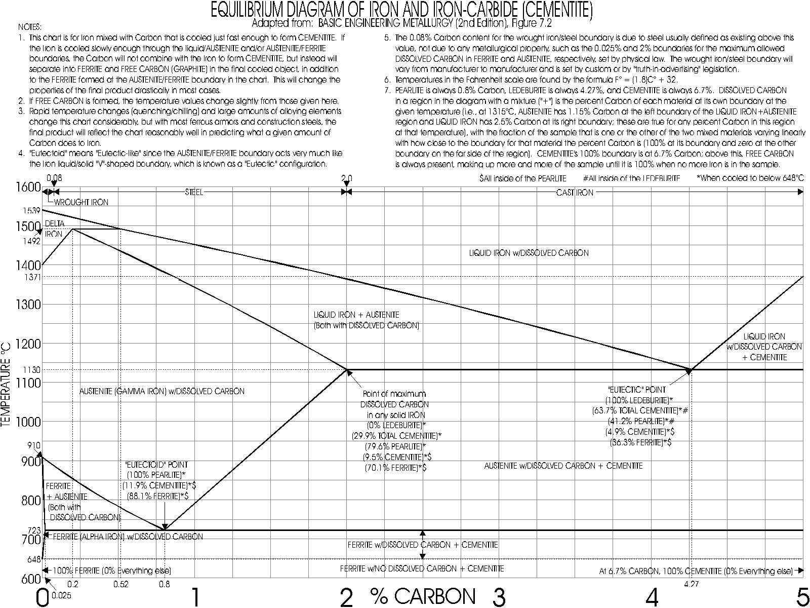
. . . . If Carbon over about 0.025% by weight is added (the maximum that ferrite can hold internally at any temperature) and mixed evenly into otherwise pure liquid Iron, things change radically. When ferrite is heated about 723o Celsius (1333.4o Fahrenheit), known as the Critical Temperature (which I will call the "Critical Hardening Temperature" or CHT to ensure no confusion with any other "critical" temperatures), doing it in a manner that the heat is spread evenly throughout the entire sample and all changes to the Iron have time to finish occurring ("equilibrium" conditions hold), the ferrite begins to change to another crystal called austenite (see below), which can absorb up to 2% Carbon at 1130oC (2066oF) in the rather large gaps at the center or boundaries of each crystal "cell." With no Carbon in the mixture, it takes a temperature of 910oC (1670oF) to completely change to austenite, but this drops in almost a straight line with increasing Carbon content to the CHT when the Carbon content reaches 0.8%, which is the maximum amount of Carbon austenite can hold at the lower CHT. This 0.8% remains constant for all larger amounts of Carbon. When the liquid Iron solidifies, it first forms austenite and when the hot solid austenite form of Iron cools very slowly through the the CHT it dissolves the austenite and forms into crystals of ferrite (more crystals than the austenite, if the size of the crystals are the same, since fewer Iron atoms are needed per crystal "cell" in ferrite). Ferrite has no available empty spaces in its crystals and cannot internally absorb more than about 0.025% Carbon (and this much only at the CHT)--the percentage of Carbon that can be held by ferrite steadily drops toward zero when the temperature is lowered to 648oC (1198.4oF) or raised to 910oC, as the crystals contract in size as the temperature lowers or gradually dissolve and change into austenite as the temperature rises to near the 910oC point, as mentioned above, so Carbon above 0.025%, as well as many other impurities, are either forced out of the ferrite crystals into the narrow gaps between the crystals as they grow when the temperature is lowered below 910oC (usually new crystals grow from the boundaries of the previous form of crystal, when not being formed directly from the liquid Iron state, since these discontinuities act as crystalization nuclii or "seeds," which allows the size and shape of old austenite crystals to modify the size and shape of new ferrite crystals and vice-versa as heat treatments proceed) or, if the temperature drop is fast enough, some or all of the Carbon is trapped in the forming ferrite crystals and the intense pressure as the Iron atoms try to form into ferrite causes the trapped Carbon atoms to chemically combine with the Iron atoms to form cementite (see below)--cementite is "metastable" in that if the temperature is again raised to form austenite, it begins to break up back into austenite and Carbon (the higher the temperature, the faster this breakup happens) and the Carbon can be re-absorbed by the empty spaces in the austenite crystals. However, the Carbon may have been physically moved by the austenite-to-ferrite change and no longer be evenly spread through the metal, so narrow regions near the old ferrite crystal boundaries may have too much Carbon to absorb immediately, while other areas have almost none--if one waits long enough, however, the Carbon will slowly move (diffuse) through the hot austenite and more evenly redistribute itself due to the Brownian motion (intense vibrations) of the hot Iron and Carbon atoms, which are no longer held in place by the Iron atoms; this is the basis of the hardening technique called cementing (described below). If the austenite with Carbon is cooled rapidly through the CHT, much less Carbon has time to move out of the forming ferrite crystals and much more of it forms cementite (extremely rapid cooling of Carbon-containing austenite can form a third crystal structure called martensite (see below), but this is not formed at anywhere near the "equilibrium" conditions being discussed here), depending on the size and shape of the original austenite crystals, how much Carbon is in the mixture, and how fast the cooling occurs--other alloying elements added to Iron are primarily used to adjust the rates of change and final crystal structures to increase the ease (and/or reduce the cost) of manufacture (or even to allow some kinds of crystal structures to be created at all). Iron with Carbon between the minimum 0.025% (usually the practical minimum is set at 0.08% and any Carbon less than this is merely considered an impurity in the otherwise Carbon-free "pure" Iron) and the maximum 2% is called steel and is the most widely used and versatile form of Iron. Most of the following discussion is how to manipulate steel by heat treatments, alloying it with other elements beside Carbon, and mechanical working.
. . . . As the percentage of Carbon is increased from zero, the melting point of Iron drops rapidly in a nearly straight line from 1539oC (2802.2oF), nearly as high as Platinum and very expensive try to reach in a manufacturing plant, to 1130oC (2066oF) at very close to the 2% Carbon point, with only partial melting of the austenite occuring at temperatures above this line until a second, higher, nearly straight line of total melting occurs from 1539oC at zero Carbon to the 1130oC level at 4.27% Carbon, above which the melting point stays constant, at least through 5% Carbon, which is as high as we need worry about here. (Note: Iron initially has a third crystal structure called "Delta Iron" if the Carbon content is below 0.52%, but this turns into austenite when the temperature drops below 1400-1492oC (2552-2717.6oF), depending on the Carbon content, so it is of no significance to us.) When put on a graph with temperature increasing vertically and Carbon content increasing to the right, both linearly, this mixed liquid/solid region looks like a shark dorsal fin curving up to the left with its tip at zero Carbon and 1539oC. When more than 4.27% Carbon is used at just above 1130oC, the extra Carbon solidifies (precipitates) either as free Carbon (graphite, described below) and ferrite or as cementite, leaving the remaining liquid at the 4.27% Carbon level (this need not concern us any more here). When less than 4.27% Carbon exists at just above 1130oC, down to the 2% Carbon point where solid austenite replaces all of the liquid Iron, some of the liquid will precipitate at austenite with 2% Carbon in it, again leaving some liquid with 4.27% Carbon. The amount of liquid left over in the 2-4.27% Carbon range just above 1130oC is simply directly proportional to how far the actual Carbon content is away from the 2% solid value--if the Carbon content is, say, 3.135%, which is exactly halfway between the 2% solid austenite and 4.27% liquid Iron points, then exactly half of the Iron is liquid and half is solid 2%-Carbon-containing austenite, mixed together in random blobs and swirls. This same rule works for any fixed-temperature level within the mixed solid/liquid region. Simply note the Carbon contents at the two boundary points where this region is cut by the horizontal temperature line and any solid in the mixture will have the Carbon content of the solid austenite at that boundary at that temperature and any liquid will have the Carbon content of its boundary point. The only thing changing will be the fraction of the metal that is liquid (the rest is all solid austenite) and that is found by calculating the ratio of (how far from the solid austenite boundary the Carbon content is) over (the Carbon content difference between the two boundary points). For example, 1315.6oC (2400oF) is the temperature of complete melting for 2.5% Carbon, while at this same temperature, the solid austenite boundary is at about 1.15% Carbon. If you have an Iron sample at 1315.6oC with, say, 2% Carbon in it, the solid austenite part has 1.15% Carbon, the liquid Iron part has 2.5% Carbon, and the percentage of the sample that is liquid is (100)(2-1.15)/(2.5-1.15) = 850/1.35 = 64%, with the rest solid austenite, all more-or-less randomly mixed together (the points where melting occurs are like points where crystals start: "seeds" where there is some difference from the surrounding points that makes it easier to change there).
. . . . Note again that the changes have to be made slowly enough for the material to adjust to them before an significant change occurs. In real life changes are made faster than this in most cases (time is money!), so some parts of the metal will change faster than others due to uneven heating/cooling or not enough time to allow complete diffusion or precipitation, but in many cases the rates of change are close enough to the ideal values given here to allow a good estimate as to what to expect at the end. When really fast changes are used, this is no longer true and more complex ways of diagraming the results are needed.
. . . . If the Carbon content is over 2%, the metal is called cast iron. It is made up at room temperature by ferrite, cementite, free Carbon, pearlite (described below), and/or a combination crystal of cementite and pearlite called ledeburite (see below). As with steel, if the cooling rate of the cast iron is very slow, a considerable amount of free Carbon is squeezed out of the Iron crystals into the gaps between them (forming grey cast iron made up mostly from ferrite crystals with Carbon "chips" in-between), while a more rapid cooling rate will retain more of this Carbon, creating cementite and, in turn, more ledeburite (forming white cast iron), which always contains 4.27% Carbon, essentially all in the form of cementite--this fixed 4.27% is the result of all other Iron and Carbon having already solidified out of the liquid prior to the ledeburite forming, keeping the liquid Iron at exactly 4.27% Carbon. Only this liquid at the 1130oC point will form ledeburite as it solidifies, so the percentage of ledeburite in the final object will depend only on the amount of liquid Iron--no liquid or ledeburite at 2% Carbon (all ferrite and cementite and/or free Carbon) and 100% liquid and ledeburite at 4.27% Carbon (the amount of ledeburite formed decreases above 4.27% as the amount of external cementite increases)--minus any ferrite and free Carbon formed from the liquid due to using a very slow cooling rate--with the part of an under-4.27% Carbon cast iron that was solid austenite being formed exactly like 2% Carbon steel under the same conditions, all swirled together to complicate things.
. . . . Cast iron is usually very brittle and not as strong as steel, but its low melting point of 1130oC allows cast iron to be rather easily liquified and poured into molds, creating many very inexpensive Iron products that would be hard to form by manipulating a solid piece of hot Iron--cast steel is also used for this reason, though it takes a higher temperature to melt it and only a rather small percentage of steel objects are made by casting. Cast iron is also a good material for handling compressive loads and damping vibrations, if they are not too violent, and this is why it has been used extensively for mounts supporting shipboard equipment from the deck. The main drawback for using cast iron or cast steel in armor is the inability to use any kind of mechanical method to alter the crystal structure after casting, since the object cast cannot be deformed, especially cast iron. As a result, the crystal structure tends to be even more coarse, irregular, and brittle than it otherwise would be, limiting further heat treatments to rather mild ones if cracking due to thermal stress is not to occur. Most cast armor is hardened directly from the molten state to prevent such stress build up (see chilling, below), but post-hardening tempering heat treatments are limited, since most cast armor is rather thick (which is one of the main reasons casting was used in the first place) and heat treating the center of thick objects is difficult even with more ductile materials. This makes the final cast steel or cast iron product even more brittle. Another point is that most post-hardening heat treatments result in at least some softening of the cast iron and even the hardest form of chilled white cast iron is too soft (well under 500 Brinell) to allow much softening if it to perform its function (it is possible to make a rather soft, ductile form of cast iron called malleable cast iron by reheating and extremely slowly cooling a white cast iron object, but this is not a process used with armor). Cast armor is only used when a somewhat lower grade product is acceptable and increased speed or reduced cost of manufacture is more important (for example, late- and post-WWII cast steel tank armor, though even here welded rolled steel armor was preferred) or there is no other way to manufacture the item (see GRUSON CHILLED CAST IRON armor, below).
. . . . I. CRYSTAL STRUCTURE:
. . . . A crystal (also called a "grain") is made up of one or more elements or compounds whose atoms or molecules are placed in repeating sequences, so that inside a single crystal of the material the structure in one place is virtually identical to that in another, except for any imperfections or irregularities like missing atoms, extra atoms, twisted crystals where entire planes of atoms are missing or extra planes wedged into the crystal, and dirt mixed into the crystal--there are even crystals that have other crystals imbedded in them or that are formed by mixtures of other crystals. It is these embedded/mixed crystals that are the major forms of crystals in steel and cast iron and give these metals their many properties. Each repeating building block or structure is a "cell" and the entire crystal is made up of these cells repeating themselves many millions of times. Each crystal starts a some point where a "seed" makes that point somehow different from the surrounding material in such a way that it is slightly easier for the atoms of Iron and/or other element or compound to grab onto an adjacent atom or molecule and begin weaving the crystal structure outward until it runs up against the edge of the object or up against other similar crystals that are also growing outward from "seeds." Note that a seed can be almost anything, but that it is necessary to have a seed to start a crystal; if not, it is possible to super-cool a material well below the temperature that the material normally forms the crystals at and the material will still remain in its original state until something happens to force a point in the material to change its properties enough to act as a seed, at which time a very rapid crystalization will occur, sometimes allowing unusual properties not present when the material forms its crystals immediately at the time that the temperature went below the crystal-forming critical temperature. A rapid drop in temperature that is much faster than the rate of crystal formation can cause a similar effect, which is the primary method to harden Iron with Carbon.
. . . . The crystals that form are not oriented between themselves and are tilted and/or offset from each other in every possible manner. This, plus the fact that there will usually be small gaps, dirt, excess Carbon, and so forth at the edges of Iron crystals, makes the strength of the crystal internally usually much higher than the binding strength between separate, adjacent crystals. Therefore, making any kind of failure process of the material have to pass through as many different crystals as possible by reducing the size of the average crystal will toughen and strengthen the material markedly. Alternatively, making the crystals large so that they have the least number of boundaries that a crack or tear must jump across to split the material apart, will weaken the material and render it more brittle. If the crystals are made round, then the material will be rather soft, since the crystals can move past each other easily. If the crystals are irregular in shape and size, then some spots will be stress points where the crystals are pressing harder against one-another and some places on the crystal that are sticking out are liable to break off, reducing the strength compared to a force that must pass through the maximum volume of each crystal; both factors making the material much more brittle. If a kind of crystal is excessively hard and brittle, mixing it in the proper way with tough and ductile crystals can combine the best of both types and result in a material better than either one by itself. Therefore, by selecting the kinds of crystals properly and interlocking them in the optimum manner, many different properties can be achieved in Iron and steel alloys from the same basic building blocks. Actually doing this took many years of hard, trial-and-error work during the 19th and 20th Centuries and new steel manufacturing methods are being developed to this day.
. . . . The various defects in a crystal are formed, deleted, changed, and moved about during heat treatment and mechanical working and these imperfections give Iron alloys many of their best (and worst) properties. In fact, the reason a yield point exists is that these defects move as a crystal deforms and tend to jam together, locking their atoms in place, until the force gets strong enough to tear them free--each tiny crystal thus deforms in small jumps, being locked into a fixed shape in-between. Ductile failure is smooth only when viewed at a distance. A metal object made from a single perfect crystal would have properties different from the same object made using the regular compositions, forms, and sizes of crystals now in use. Crystals near the boundary conditions where they form or dissolve (depending on the direction of changing temperature) will grow until they run into one-another and then they will continue to grow by cannibalizing each other--one crystal stripping adjacent crystals of their atoms and adding them to its outer edge--until, theoretically, a single huge crystal could form, though very slowly in most cases (small single-crystal metal objects, such as jet engine compressor blades, are manufactured today due to special techniques that speed up crystal growth, but limit it to only the "seed" that the manufacturer has put into the mold to start the crystalization process). This crystal growth is another limitation put on the time that certain heat treatments can be applied, if crystals of the wrong size are not to result. The effects of alloying elements on this factor, such as slowing or speeding up this process, is another reason that they are used.
. . . . . . . . FERRITE: Body-centered cubic structure. This means that each of its cells is composed of a cube of eight Iron atoms in the corners, with a ninth Iron atom in the exact center of the cube. Each corner Iron atom is the corner of seven more adjacent cells (except if the atom is at the edge of the crystal) and these cells stretch in all directions until the edge of the crystal is reached. This structure is very isotropic (the same strength in all directions) and the Iron atoms merely reform new cells if the crystal is deformed and any existing cells are broken, allowing the crystal to be very tough (in the sense of being crack-resistent, not in the sense of being hard to deform, since wrought iron, which is almost all ferrite, is relatively easily pulled apart) and ductile and only split apart when the deformation physically separates one part of the crystal from another part, which merely results in two smaller, stretched ferrite crystals where one existed before. Brinell hardness of about 80-100, depending on crystal size/shape. Can internally contain up to 0.025% Carbon at 723oC, but none at room temperature.
. . . . . . . . AUSTENITE: Face-centered cubic structure. This means that eight Iron atoms make up the corners of each cell, as in ferrite (see above), but the center is empty, allowing small atoms like Carbon to fit inside, though when one does it enlarges the cell somewhat and makes the similar openings in adjacent cells more tightly closed, limiting the number of Carbon atoms allowed inside to a maximum of 0.8% of the total weight of the metal at 723oC and a maximum of 2% at 1130oC due to the thermal expansion of the metal opening the cell holes enough for more Carbon to fit before they squeeze close the remaining holes. Instead, each of the six sides of the cell has a fifth Iron atom at its center in an "X" pattern, so the cell contains 14 Iron atoms rather than nine (fewer cells per volume of crystal than ferrite) and the cells are each somewhat larger (further reducing the number of cells per volume of crystal). This crystal is the densest form of Iron. The crystal is just as isotropic as ferrite, but it only exists normally at a higher temperature, so it is even more ductile. Many steel mechanical working processes are done to Iron in its austenite phase since only here is it soft enough due to the elevated temperature to do so. Brinell hardness of about 110 (estimated).
. . . . . . . . CEMENTITE: A compound of Iron and Carbon, Fe3C, formed by internal pressure when austenite (see above) turns into ferrite (see above)and it will eventually turn back into ferrite or austenite and free Carbon (see below) if it can, though it can remain stable for a time inside austenite at just above the CHT (the higher the temperature, the faster it breaks down into austenite and Carbon). At below the CHT, it can remain stable indefinitely in most cases, though some forms of Iron will gradually "age" and change their internal structure as they undergo stresses from their own weight or from applied forces as they are used. Contains 6.7% Carbon. Each cell is made up of a triangular pyramid with the three Iron atoms forming an equilateral triangle base and the Carbon atom forming the top point of the pyramid. These pyramids are interlocked by bonding of the Iron and Carbon atoms into an intricate pattern of interlocking diamond shapes of Iron set into a rectangular array of Carbon atoms. This multi-facetted array of triangular shapes is extremely rigid, strong, and hard, but also extremely brittle. It has planes of weakness and once a Carbon/Iron or Carbon/Carbon bond breaks, it usually cannot be restored, allowing cementite to suffer catastrophic failure if the applied force ever exceeds the yield strength of the material. Cementite supplies the primary strength of steel and cast iron, while the ferrite supplies a cushioning and support role to keep the cementite from being directly impacted--much like even a single layer of paper can prevent brittle glass objects from breaking when they touch each other during shipping, while without the paper even a seemingly slight impact can cause the glass to shatter. Cementite is white in color. Brinell hardness of about 794 (an extrapolated value equal to 68 RC, the highest RC value).
. . . . . . . . FREE CARBON: This is the only other form of Carbon in steel or cast iron and it usually is in the form of graphite, an extremely soft, weak, and slippery form of Carbon that is used as a lubricant and has some of these same properties in steel and cast iron when it forms. It can make cast iron and steel more brittle when compressed between irregularly shaped crystals, as in grey cast iron, but it can have the reverse effect if it forms between rounded crystals where it is free to move when put under pressure. For example, malleable cast iron (never used in armor) is made from hard white cast iron by heating the object to 927oC (1700.6oF)--well above the CHT--and holding it there for 50 hours until much of the Iron and Carbon has separated and then very slowly cooling it. It has many of the properties of low-Carbon steel even though it has a large amount of Carbon in its structure, almost all of it as large lumps ringed with thick ferrite (see above) shells sprinkled within a matrix of rounded pearlite (see below) crystals, while retaining the advantages of the low melting point of the original white cast iron when originally shaping the object by molding rather than by hammering, rolling, or forging. On the other hand, grey cast iron is made of very slowly cooled cast iron directly from the liquid state, so that the Carbon and Iron only partially mixes together as the metal solidifies and continues to cool very slowly through the austenite phase and past the CHT to the ferrite phase; most of the Carbon remains in the cracks between the ferrite crystals in strips and moderately large chunks or chips, where it renders the metal very brittle without increasing the hardness or strength of the metal very much, with only some pearlite being formed from the Carbon that did mix with the Iron as it cooled.
. . . . . . . . PEARLITE: Crystal always containing 0.8% Carbon--in the form of 88.1% ferrite and 11.9% cementite (see above) in an interleaved pattern similar to straight zebra stripes. It forms naturally in slowly cooling steel and cast iron. The ferrite and cementite complement one-another to make this a very good basis for making strong, yet ductile and tough, steel. Named after the way the tiny layers act as a diffraction grating to give a rainbow tint to the material under a microscope. Hardness increases as the original mixture's Carbon content or the cooling rate increases, as long as the transformation temperature does not fall below 538oC (1000.4oF), where another crystal bainite (see below) replaces it. As the 538oC boundary approaches, each pearlite crystal formed is harder and has thinner and more numerous stripes until at the boundary the metal seems to be a uniform grey color. The fixed 0.8% Carbon content is due to that being the Carbon content of austenite (see above) just above the CHT for the same reason that ledeburite has 4.27% Carbon: Above 0.8% Carbon, the excess Carbon will precipitate out of the austenite as cementite or free Carbon (see above), though at a much slower rate than with a liquid/solid transformation, while below 0.8% Carbon, but above the 0.025% Carbon that ferrite can contain at the CHT, ferrite will slowly precipitate out until only 0.8%-Carbon austenite is left. Unless the cooling rate is so slow that ferrite and free Carbon form instead of cementite, pearlite will be formed directly from the austenite as the ferrite portion forms, coated with the extra ferrite, if under 0.8% Carbon, or extra cementite, if over 0.8%.
. . . . . . . . LEDEBURITE: Crystal made up of pearlite (see above) lumps imbeded in a matrix of cementite (see above). Nearly white in color. Contains 4.27% Carbon. Forms the major component of white cast iron and is created by cooling Iron with over 2% Carbon from the liquid state using a chilling process of some sort to prevent the formation of grey cast iron, which is created directly from liquid Iron by very slow cooling by breaking up cementite into ferrite and free Carbon (see above). Hard, but the existance of the relatively soft pearlite within it reduces the hardness compared to the cementite and martensite (see below) of high-Carbon steel that has been quenched in an optimum manner. Rather brittle, but less brittle than grey cast iron due to the extensive pearlite content. When the cooling rate is relatively slow, the pearlite lumps are rounded and look a lot like watermelon seeds, alternating with long zebra-stripes of pearlite, imbedded in the surrounding cementite matrix. When a very rapid chill is used, the stripes replace the seeds and the stripes get very thin and bunched into bundles that look like many black and white toothpicks of varying sizes packed together parallel to each other. The bundles from different crystals are jammed into each other at various angles, so that the white cementite is not obviously the surrounding medium (matrix) and any cementite and ferrite formed prior to the chill from the original liquid (when the Carbon content is not 4.27%) are bound tightly with the new cementite and ferrite formed inside the ledeburite to the point that they all seem to be the same. Makes up most the face layer of GRUSON CHILLED CAST IRON Armor (see below), which probably had about 4% Carbon (typical). Brinell hardness can be from about 425-500, with the deep chilling needed for the Gruson armor requiring a rapid surface cooling that would tend to give the surface a higher hardness, estimated circa 475 Brinell.
. . . . . . . . BAINITE: Similar to pearlite (see above) when viewed under a microscope, though somewhat more random in its striping (more like a leopard than a zebra). Occurs when the cooling rate is fast enough so that the transformation from austenite (see above) occurs in the range 260-538oC (500-1000.4oF), with the lower the temperature, the more irregular, finer-grained, and harder it becomes. Near the 538oC boundary where pearlite stops forming, bainite is more brittle than pearlite without being much harder--this is called upper bainite due to the higher temperature of transformation--note that temper brittleness (see TEMPERING, below) occurs in the 371oC (699.8oF) to 650oC (1202oF) range, which neatly boxes in upper bainite, indicating that they may be related. The 260oC boundary is where martensite (see below) forms instead of bainite. Just above this boundary, the form of bainite is termed lower bainite and it has many of the properties of martensite and is even used in martensite's place when brittleness is not a major criteria using a hardening technique called austempering. Bainite has its cementite grains arranged in an elongated "fern-leaf" (radiating rib-like) pattern--with the lower the formation temperature, the smaller and finer the pattern--that does not allow complete spheroidization, so tempering it does not work as well as with martensite. Bainite can also form when the quenching process is not carried out long enough to drop the temperature below the 260oC boundary to fully form martensite. Because upper bainite is relatively brittle without any advantage over pearlite, it is not desired in any kind of armor. The formation of upper bainite in the center of very thick plates of Japanese VICKERS HARDENED non-cemented face-hardened armor (see below) due to the use of the old pre-WWI Vickers version of the KRUPP CEMENTED (see below) hardening process, which was never designed for such massive plates, caused them to split in two on impact, giving a perfect example of why this crystal structure was not desireable.
. . . . . . . . RETAINED AUSTENITE: If the Iron above the CHT is suddenly cooled to 260oC (500oF) or less, its atoms cannot move prior to being frozen in place, so the austenite (see above) face-centered cubic structure remains. This also occurs at higher temperatures when the Carbon content of the metal is significant, but the time that it takes for the austenite and Carbon to change to the final lower-temperature form (pearlite or bainite (see above) or white martensite (see below)) varies enormously. Assuming the simplest case of 0.8% Carbon, when the temperature is held barely below the CHT will it will take a long time (many hours) for austenite to change toferrite (see above), resulting in pearlite when it finally happens. When the temperature is dropped very rapidly to about 570oC (1058oF) and held there (the transformation temperature or "Hold Temperature"), it only takes about 0.8 second to begin to change to pearlite and 4.8 seconds for it to completely change. When the highest bainite temperature is reached as the Hold Temperature--538oC (1000.4oF)--this is not changed by much, but as the Hold Temperature drops further, the time before transformation starts begins to increase again, but much more slowly so that it is only about 35 seconds at 260oC (500oF), the lowest bainite temperature, while the time to complete transformation to lower bainite at 260oC increases to almost 20 hours. When the Hold Temperature goes down to just below 260oC, a strange thing suddenly happens: The transformation from austenite stops happening and it will remain austenite indefinitely! As the Hold Temperature continues to go down, martensite begins to form instantly on reaching that temperature, with a fixed percentage of the austenite changing to white martensite at each Hold Temperature, no matter how long the temperature remains there. As the Hold Temperature continues to drop, the percentage of white martenite increases until all of the austenite is changed to white martensite instantly on reaching -73.3oC (-100oF). (The percentage of white martensite that is created is not a linear relation with decreasing Hold Temperature, but increases slowly near 260oC and -73.3oC and increases very rapidly in the middle, with 93.3oC (200oF) being the 50% transformation point.) The percentage of retained austenite at room temperature is about 20%--to eliminate this requires dropping the temperature of the object the rest of the way to -73.3oC for a short time to change it to white martensite or going back up to a near-CHT tempering temperature to change it to pearlite. Since austenite has a cell ofabout 3.57A (angstroms, each one-hundred-millionth (10-8) of a cm) on a side (larger when heated to near-liquid temperature) and ferrite only has a cell size of 2.87A, the force on this structure as it tries to turn into ferrite is enormous, greatly increasing the brittleness of the metal. If the retained austenite is at room temperature after a quench to form whitemartensite, it also has the property that it will change spontaneously to white martensite, an even more brittle material, if the temperature drops (winter setting in or moving the object aroundin the ocean to near the North or South Pole), so the object is unstable from that angle also. The lower the Carbon content of the steel, the faster the initial temperature drop rate must be to form martensite and the harder it is to achieve, so the smaller the proportion of white martensite and the larger the proportion of retained austenite. Tempering has as one of its major goals the removal of this "retained" austenite so as to toughen and stabilize the metal. Note that some alloying elements lower the CHT to the point where austenite forms at room temperature regardless of the cooling rate, which obviously eliminates most heat treatments.
. . . . . . . . MARTENSITE: Martensite has two forms: Fresh or white martensite, formed by the initial strong cooling to 260oC (500oF) or below from austenite (see below), and tempered or yellow martensite, formed by a breakdown of white martensite into cementite and ferrite (see above) in a unique pattern. White martensite forms under the same conditions as retained austenite (see above), with virtually none forming at the 260oC temperature (all retained austenite, instead) and a steady increase in percentage as the temperature of transformation drops until virtually all of the austenite turns into white martensite at -73.3oC (-100oF); this transformation is essentially instantaneous, unlike the transformation of austenite to pearlite or bainite (see above), which may take some time if not assisted by various alloying elements (see RETAINED AUSTENITE, above). White martensite is a face-centered tetragonal crystal, which has each cell consist of a rectangular prism (not a cube) 2.84A by 3A (for a 0.6% Carbon steel; both axes get larger as the Carbon content of the crystal increases)--compared to austenite's usual cube of 3.57A (larger when Carbon is mixed in with it) and ferrite's 2.87A--made up of the eight original corner austenite Iron atoms forming a "cage" around a diamond shape made of the austenite's original six center-face Iron atoms now chemically bonded to the central Carbon atom that was in the austenite cell when cooling began (cells without the central Carbon atom also become white martensite but they are not chemically bonded, just locked into the shape by their chemically-bonded neighbors)--this diamond shape, longer than it is wide, is also one of the main components in cementite, so white martensite cells with Carbon in them can be viewed as cementite being formed inside of a ferrite crystal. The lower the Carbon content, the fewer chemically-bonded cells with Carbon in their centers exist and the more difficult it is to lock the white martensite shape into the crystals, so the faster the initial temperature fall must be to freeze in the austenite cell shape on which the white maternite cell shape is based. Conversely, increasing the Carbon content allows a slower quenching/chilling time to reach the white-martensite-forming temperature range desired and results in an increased hardness (more white martensite forms) for a given cooling rate. Various alloying elements, such as Chromium and Molybdenum, do this too, which is the only reason that high hardening levels used in deep-faced, KC-type face-hardened armors are practical with low-Carbon-content (necessary for adequate toughness) armor steels. White martensite is even more unstable than retained austenite and as brittle as glass and it will gradually break down into tempered martensite, though the rate of breakdown can be very slow--this may be a good trait in old Japanese swords, but not in production armor! By reheating the retained austenite/white martensite combination to near, but below, the CHT and holding it there for a time that depends on the temperature and the thickness of the object, both the retained austenite and the white martensite can be very rapidly changed to pearlite and tempered martensite, respectively, as well as allowing the metal to get the other benefits of tempering. Tempered martensite is much less brittle than white martensite and its crystal structure has oval lumps of cementite of many sizes formed into a series of rows (with very small cementite lumps randomly sprinkled around the rows) in a ferrite matrix (surrounding material), somewhat similar to pearlite with very fat, broken-up cementite layers--the higher the Carbon content, the higher the percentage of cementite and the harder the final product for a given cooling rate, though the hardness increase slows as the Carbon content approaches 0.8% and above, where the maximum possible hardness reaches an extrapolated 794 Brinell. This value (equalling 68 RC) can be compared to the absolute maximum Brinell Hardness Number that can be measured of 739 (65 RC) and the usual maximum value of 700 Brinell (62.8 RC) attainable in any repeatable production process and it is rarely attempted; the cemented layer's (see CEMENTING, below) surface hardness in Krupp's KRUPP CEMENTED (KC a/A and n/A) armors (see below) is the only time that even the hardest face-hardened armor has reached 700 Brinell and even here this was done only in the 1-1.5% Carbon cemented layer by special processing and it was above the average of 670-680 Brinell (61-62 RC) maximum for most plates made by Krupp and well above the average of 650 Brinell (60 RC) maximum used by most other manufacturers of KC-type armor, with the lowest cemented layer hardness being in British WWII CEMENTED ARMOR (see below), with its unique circa-600 Brinell (RC 58) maximum. Increasing the amount of Carbon above 0.8% does make the steel easier to harden to a given level, but it also makes its much more difficult to toughen the metal to an acceptable level, so armors never used over 0.55% Carbon--the average was 0.3-0.4% Carbon--except for the thin cemented surface layer of HARVEYIZED MILD- or NICKEL-STEEL (see below) and KC armors, which was immediately destroyed by the projectile impact, anyway. By using other alloying elements to enhance the steel's hardenability (wringing out the maximum effect for a given amount of Carbon), rather high hardness was possible without increased brittleness due to using more Carbon.
. . . . II. HEAT TREATMENTS:
. . . . Hardening cast iron and steel is done by rapidly cooling the object being made either in its entirety or on one surface of the object to harden the portion being so cooled due to the formation of higher hardness (and higher strength, though also higher brittleness) forms of the various crystal structures mentioned in I. CRYSTAL STRUCTURES, above. Some of these heating and cooling techniques, such as tempering, can reduce hardness and increase toughness, so making steel is a sometimes complicated process of many steps.
. . . . . . . . CHILLING: Cast iron and cast steel are hardened usually directly from liquid state by using a regular insulating mold for the portions of the object to be kept soft, so that these portions only gradually cool down to grey cast iron or pearlitic steel, while those portions to be hardened into white cast iron or martensitic steel are shaped by a mold made of a material that is highly conductive to heat and which is kept cool by having water or other material on its far side to carry off the heat--wrought iron or very low-Carbon steel is used for the chill, as the portion of the mold that is conducting is called, in most cases due to its high melting point and its ability to retain its original shape until the object being cast has cooled down. GRUSON CHILLED CAST IRON armor (see below) was the only major face-hardened armor made this way, but various small armor-steel fittings (cowls protecting sighting and range-finding gear sticking out of turrets, for example) have been made using chilled, face-hardened cast steel. The control of the temperature deep in the object being cast is not as good as with other cooling methods, so chilling is only employed when the details of the process are not critical and a relatively wide tolerance is allowed in the final results--the exact depth of face in the Gruson armor was not critical and matching an exact hardness pattern also was not necessary, since there is a rather wide range of values for the hardness and depth of face that give virtually identical results in face-hardened armor.
. . . . . . . . QUENCHING: Forged, rolled, and hammered steel hardened after previous mechanical and heat treatments have shaped the object to essentially its final form (only a small amount of machining for a tight edge fit with an adjacent plate in the case of armor and so forth will be done after hardening) and adjusted its crystal structure to that considered optimum (or at least acceptable) for the final product. Part or all of the object is heated above the CHT and then rapidly cooled by one or more of the following methods: Dipping the portion of the object to be hardened in hot or cold water; spraying that portion and, to prevent cracking due to thermal stress, usually the rest of the object with high-pressure water; dipping it into hot or cold oil; and dipping it into molten lead. These various methods control the final temperature (highest in lead and lowest in cold water) and the rate of heat removal (highest in cold water or, for large, thick objects, with the water spray--since steam formed can interrupt the cooling rate and the spray keeps the steam cleared away--and lowest with molten lead). For some objects, including some forms of face-hardened armor and most armor-piercing projectiles, several methods were used to reach the final hardness pattern and crystal structure.
. . . . . . . . ANNEALING: This is the opposite of chilling and quenching; here the object is softened to prevent cracking or to improve machinability by forming less cementite from the available Carbon. The thoroughness of this effort varies considerably. Normalizing is a form of mild annealing where the object is heated to a fixed temperature above the CHT and then allowed to cool down in open air by itself until it has reached a relatively low temperature (usually room temperature). This gets rid of many of the stress points in the metal after initial pouring and shaping and is usually the first step in the final manufacturing processes to turn the object into its final form--sometimes this step is repeated several times between various manufacturing processes to return the metal to a known baseline state. Full annealing is a deliberate, usually long-lasting, process of heating to very specific temperatures and then slow cooling in one or two ovens to specific final temperatures to ensure that the metal changes its structure at very specific temperatures, which controls crystal (grain) size and the softness, ductility, and toughness of the final product. This is the technique used on white cast iron to form malleable cast iron and it is an exacting process. Unlike quenching or chilling, these techniques even work with wrought iron, since stress points in the crystal structure can exist without anything to do with Carbon and thus annealing can reduce brittleness and make a more uniform final product.
. . . . . . . . CEMENTING: By either packing a steel plate's face tightly against bone charcoal (the original "Harveyizing" technique also used by most makers of versions of KRUPP CEMENTED-type armors (see below)) or by continually spraying the face with methane ("illuminating") gas (Krupp's version of this process), in either case in an air-tight oven raised to well above the CHT, the carbon would slowly soak into the austenite to a depth of about 1" (2.54cm) over a period of about 2-3 weeks, raising the carbon content to about 1-1.5%, which can easily be quench-hardened to the hardest kind of martensite afterward. Introduced in armor as HARVEYIZED NICKEL-STEEL armor (see below) developed in 1890-91. Increased the surface hardness of any Iron or steel material, including Mild Steel, to 600-700 Brinell with no significant change to the rest of the plate after quenching the face (see HARVEYIZED MILD STEEL armor, below). Also known as case hardening or carburizing and widely used to get wear-resistant surfaces on items like ball bearings. Cementing is a very old method for hardening iron objects, originally using the technique of burying the object in the hot coals of the wood-burning furnace and leaving it there with the furnace kept at a high temperature.
. . . . . . . DECREMENTAL HARDENING: This is a special form of quenching designed to get a deep, gradually-softening face on a face-hardened plate. Gruson Chilled Cast Iron armor formed its face using the chilling process, which was possible because of the very high Carbon content of the cast iron allowing rather rapid hardening. However, armor steels use rather low amounts of Carbon to prevent brittleness, so deep hardening is only possible by the use of alloying elements--primarily Chromium, though Molybdenum was used extensively after WWI in addition to Chromium--that slow down the transformation of austenite to ferrite, allowing martensite to form deeper in the plate where the cooling rate is slower, and that form additional carbides to increase the hardness by more efficiently using the existing Carbon. Nickel was also of use here, since it toughened steel considerably and allowed higher hardnesses to be used while keeping the toughness above the minimum required. This process applied to steel was introduced by Krupp in 1894 as his famous Krupp Cemented face-hardened armor (later called KRUPP CEMENTED "OLD TYPE"--abbreviated "KC a/A" (see below)--in Germany after WWI to separate it from the improved KC "NEW TYPE" ("KC n/A" (see below)) developed by Krupp during the late 1920's and early 1930's) and in less than a decade had made all other forms of metal armor obsolete when used for the primary protection of warships and, later, armored land vehicles--including all previous homogeneous metal armors because his new Chromium-Nickel-Steel was harder and tougher and thus more resistant than the older Nickel-Steel. It was originally combined with the cementing process, but some face-hardened armors dispensed with cementing and successfully employed decremental hardening by itself. Except for a final, post-hardening temper (not always used) and minor machining, the decremental hardening process was the last heat treatment applied to a face-hardened armor plate. The plate was completely heat treated for optimum crystal structure, mechanically worked (hammered, rolled, and forged), cemented (if used), and shaped to as close to its final form as possible, then laid flat and packed around the edges with an insulating layer of sand or loam, so only its face and back surfaces were exposed. Any portions of the face where holes were to be cut were covered with thick insulation (usually asbestos) to reduce both the rates of heating and of cooling and thus prevent hardening when quenched. All temperature and times used were carefully regulated using data from previous tests and production runs. The plate was run into an oven and raised slowly to an even red hot temperature below the CHT, then the face surface only was evenly blasted by flaming jets to raise it to a much higher white hot temperature and the plate allowed to soak in this condition for a specified time, depending on the plate size and thickness. The CHT would gradually move into the plate in a flat front and when the timer indicated that it had reached the desired depth (which varied considerably between manufacturers and date made over a wide range), the plate would be removed from the oven and either both the face and back would be sprayed with high pressure water cold (original Krupp technique) or the plate would first undergo dipping of the face in water and/or oil (British Vickers KC-type armor manufactured prior to WWI, for example) prior to the final water quench. The result was a "decrementally hardened" or "deep" face layer of circa 500 Brinell (535 Brinell is the hardest I know of) just behind the cemented layer (if used), dropping off gradually in hardness to the level of the unhardened back in one of several ways, depending on the final face and back temperatures, the heating time, and the plate's metallurgical makeup. The original KC a/A armor had the deep face layer's hardness drop off with increasing depth in either a straight line or a "ski-slope" (a rapid, ramp-like drop in the middle of the face layer, but slow near the surface and near the unhardened back, like a child's slide) to about 350 Brinell at about 20% into the plate from the face surface. At this point the drop in hardness would become much steeper in another ski-slope--the transition layer--until it merged with the back layer's circa 225 Brinell hardness at 33-35% of the plate from the surface of the face, being a constant hardness from there to the back surface of the plate. Except for the sudden drop in hardness at the back of the cemented layer (if used) of from 650-700 Brinell to the circa 500 Brinell level, in no place was there any sudden change in hardness, though there was the relatively sudden change in the rate that the hardness was dropping at the boundary of the deep face layer and the transition layer. The cemented layer/deep face layer combined is also called the undrillable portion of the face, while the entire cemented layer, deep face layer, and transition layer combined is called the chill or, loosely, the face, though this can be confused with the more limited scope deep face layer part of the undrillable portion of the chill. The width of the undrillable chill portion, the width of the transition layer, the hardness level where the transition layer begins, and the average hardness of the back layer were all changed slightly or considerably by later adopters of this process, including, after WWI, by Krupp itself. KC n/A armor increased the back layer hardness to 240 Brinell (the maximum used by anyone); increased the depth of the chill to 41% (very exact value); and adjusted the hardness drop in the undrillable chill layer to exactly match the transition layer drop so that the chill went from about 500 Brinell just behind the cemented layer in a single straight line or gradually-flattening curve, making the point where the transition layer starts invisible (it should be when the hardness drops to somewhere around 350 Brinell, depending on whose definition of "undrillable" you use!). This armor was tempered and was much superior to KC a/A in every way. In other face-hardened plates, the deep face layer hardness stays constant for some depth and then begins to decrease in a ski-slope (deep face layer/transition layer boundary again somewhat arbitrarily specified) or in a very sudden drop (essentially no transition layer at all). U.S. Navy BETHLEHEM THIN CHILL Class "A" armor (see below) was unusual in that it had essentially no deep face layer, with the drop in hardness being so steep behind the cemented layer that the cemented layer itself became the entire face and only a narrow, very steep transition layer not much thicker than the cemented layer connecting the cemented layer with the back layer, while U.S. Navy MIDVALE NON-CEMENTED Class "A" armor (see below) had a extreme chill depth of over 80% of the plate. The depth of the chill (actually the thickness of the unhardened back layer as a percent of the total plate thickness) is important not only for damaging projectiles, but also because the hard chill always fails by breaking (brittle fracture) and this is a surface phenomenon, as opposed to ductile tearing, where the entire volume of armor is distorted and pushed aside by the projectile as it penetrates (see SCALING on page 3).
HISTORICAL NOTE CONCERNING DECREMENTAL HARDENING: Decremental hardening is an old process. For example, it was used in Japanese swords and daggers for centuries: A low-carbon steel rectangular block was imbedded in the coals of a furnace, heated white hot, removed, folded in half, hammered back to its original shape, and put back into the furnace. This was done many times, creating thousands of thin parallel layers of low-Carbon steel alternating with high-Carbon steel from the soot adhering to the surface of the metal prior to folding. The block was finally hammered to its final, stretched shape with these layers parallel to its wide sides and polished, with the back edge of the gently-backward-curving sword thick and flat, its thickness kept constant from handle to tip (the end of the swords was beveled, since stabbing was not the purpose of the sword), and the sword body smoothly tapering cross-wise in a wedge shape to a single, razor-sharp edge where the many layers were crushed into a single mass of high-Carbon steel. A thick, even layer of hard clay was coated over the back of the sword and the thick, upper portion of the sides, with this clay layer tapering in thickness to nothing just above the blade edge. The blade was evenly heated to "the color of the morning sun" (orange; perhaps 1000-1100oC (1742.4-1922.4oF)) and then suddenly quenched in cold water. The edge became solid white martensite and retained austenite and the cooling rate slowly decreased toward the thick back due to the insulating clay, forming less and less martensite mixed with the retained austenite, then bainite, then finally pearlite, with microscopically thin layers of low-Carbon steel separating the equally thin layers of high-Carbon steel (like pages in a book) parallel to the sword's side surface down the entire length of the sword, except near the sharp edge itself. I do not know if a final temper was used after the hardening--perhaps the swords were allowed to gradually have their white martensite/retained austenite edge change to tempered martensite and ferrite due to air cooling over a long time like fine wine aging!
. . . . . . . . TEMPERING: This is the final, post-hardening, toughening process (related to annealing, but kept below the CHT at all times), where the internal stress points are allowed to smooth out and white martensite and retained austenite eliminated. It is also called drawing. Depending on the metal's composition, this process has the object heated to a specific temperature below the CHT and then cooled at a rather slow rate to another fixed, lower temperature; sometimes going up and down more than once. The most complete, highest-temperature form of tempering results in spheroidization, where the cementite crystals are rounded (into spheres, egg-shapes, or cylinders with rounded ends) and spaced apart in each ferrite crystal like seeds in a watermelon, giving the softest, toughest form of the metal for a given amount of cementite--tempered martensite is the best example of this effect. Tempering is supposed to toughen a steel object, but this is not as simple as it might seem: Chromium-Nickel-Steels have a temperature range of from 371oC (699.8oF) to 650oC (1202oF) where slow cooling during tempering of a quench-hardened steel, such as face-hardened KRUPP CEMENTED armor (see below), results in a steep drop in toughness called temper brittleness. If the tempering treatment must go into this range, it is better to quench the plate for rapid cooling until the temperature is below the 371oC value before allowing slow cooling to continue. This is not a minor point. The pre-WWI U.S. Navy MIDVALE NON-CEMENTED Class "A" armor (see below) that was able to shatter the otherwise invulnerable (at under 15o obliquity against most armors made up through 1925, that is) U.S. Navy "Midvale Unbreakable" armor-piercing projectiles introduced from 1911 (8" (20.3cm)) to 1923 (16" (40.6cm)) at right-angles impact was found to only work due to the employment of a 343.3oC (650oF) final tempering treatment--tests using a 496.1oC (925oF) final temper caused the plates to act like pre-WWI Bethlehem Non-cemented Class "A" plates (see "AVE. WWI-ERA CLASS 'A'" armor, below), which were very brittle and which were barely above the minimum acceptance level in quality (obviously, Midvale "lucked out" in using their tempering process, since temper brittleness was not understood until well after WWI, and just as obviously, Bethlehem did not have that luck). Also, tempering can result in loss of hardness, especially if it is kept at an elevated temperature for too long, since cementite is subject to decomposition into ferrite and free Carbon and, while very slow at below the CHT, this process is not infinitely slow until near room temperature (tempering in boiling water has been used at times--in Bethlehem Non-Cemented Class "A" armor, for example, in an unsuccessful attempt to increase its poor toughness--so the effects of even very modest heat treatments are not to be ignored). Tempering is the cause of the small drop in surface hardness in most face-hardened armors--the maximum hardness occurs a short distance behind the surface of the face--though Krupp made a major effort to prevent this and neither German KC a/A nor KC n/A armors, uniquely, show any significant hardness drop at the surface (KC a/A was not tempered after hardening, but KC n/A was, so this was not an accident). As with decremental hardening, tempering is an old process long used in sword making to reduce brittleness, which is where the original term "drawing" came from (e.g., drawing the brittleness from the metal).
. . . . . . . . REFRIGERATION: Cooling Iron materials below room temperature has a number of effects, some useful, though most causing problems. Cooling a white martensite/ retained austenite hardened material shrinks the crystal cells and increases forces trying to convert the material's austenite to white martensite, so it sometimes is used to try to speed up this process in a particularly stubborn, slowly-changing quenched object where tempering the existing mixture is not desired. Even in a properly heat-treated material, strong cooling at or below the freezing point of water causes the crystals to shrink, splitting them apart and making the material more brittle as it can now more easily crack apart through failure between crystals, rather than through the interior of crystals. Cooling also makes the metal more rigid, which has the effect of increasing the yield strength without, unfortunately, increasing the tensile strength by much, if at all, so that the metal loses toughness. If the toughness loss goes beyond the minimum necessary, the plate is said to have gone below its brittle-failure Critical Temperature (the lower this temperature is, the tougher the steel remains at any given temperature as it gets colder). Increasing the Carbon (see below) content makes it easier to harden steel, but it also makes it more subject to this form of brittle failure by raising this brittleness temperature, while Manganese (see below) also hardens steel, but actually lowers this temperature, which is a major reason that it is used in steel manufacture. Nickel (see below) lowers this temperature considerably; one of its many benefits. Therefore, the absolute minimum amount of Carbon should be used for any given level of hardness, with other alloying elements--preferrably those that toughen the steel and/or lower the brittleness temperature--being used to make up for any loss in hardenability. Failure of a properly toughened Iron object at room temperature when suddenly folded is called a fiber failure because the material fails by shearing apart individual crystals and has the look of a ductile tear with rather smooth edges. If the object is cooled to successively lower temperatures and broken by folding, the failure zone begins to show jagged, sharp-edged, zig-zag breaks called grain due to failure between crystals and eventually at the coldest temperatures, these make up all of the failures, with the metal being much easier to break. Good armor steel has to be cooled below about -50oC (-58oF) to begin to get grain to form, but poorer Iron/steel needs only 0oC (32oF) to get some grain.
. . . . III. MECHANICAL TREATMENTS:
. . . . Mechanical manipulation of Iron and steel, in addition to shaping it to the form needed for the final product, can modify its properties in a manner similar to, but usually less extreme than, heat treatments, due to the reshaping of the crystals in the metal by "brute force" and the localized heating and cooling of the metal on a microscopic level as it is squeezed and released, which is called work hardening--the breaking of a nail or tin can lid by bending it back and forth is caused to a large extent by the work hardening of the metal at the bending point that increases gradually at each bending cycle until the metal gets hard enough to act in a brittle manner and snap in two. Keeping the metal hot enough so that it never cools below the CHT during any mechanical treatments eliminates work hardening, though the other effects of crystal distortion and breakage remain.
. . . . . . . . HAMMERING: This is the oldest method of manufacturing soft Iron and steel, as applied by a blacksmith in making horseshoes, swords, and so forth, by hand. When the first large-scale wrought iron manufacturing plants were built in the early 19th Century they simply copied this technique using huge cast iron hammers powered by steam to lift them and gravity to drop them onto the Iron object being manufactured. It is still employed in manufacturing, but rarely for steel plates, since it is uneven, only affects a small part of the plate at each blow so that any large metal plate takes a long time to make, and can cause unwanted work hardening if the metal's temperature is not carefully controlled.
. . . . . . . . FORGING: This is a direct offshoot of hammering where, instead of pounding the metal into shape, strong pressure is applied more slowly, though sometimes again and again, to force the hot metal to the desired shape, usually using a specially-formed tip to the press called a die. This reduces the effects of work hardening and allows shaping of objects in very complex ways. Since the advantage of gravity-induced velocity is lost, the steam-, hydraulically-, or, more recently, electrically-powered presses required to get enough pressure to bend and flatten large Iron or steel objects, such a thick armor plates, are enormous in size and somewhat expensive compared to any other method of mechanically working the metal, but the results are more controllable and usually superior. All U.S. manufacturers used forging for all heavy armor, with very good results.
. . . . . . . . ROLLING: This is the most wide-spread method used for making Iron and steel plates, both construction and armor, since it gradually flattens the entire plate at one time, making the plate more even and much less time-consuming to manufacture. It has a few drawbacks, however. Any internal flaws in the metal, such as undissolved alloying element pieces or bubbles, are flattened out parallel to the plate face and thus act as laminations (gaps between layers in the plate) over a much wider area, where they can increase the chance of plate failure. Also, unless the plate is small enough to be able to fit under the rollers to be rolled sideways as well as up and down (depending on which end of the plate is defined as "up"), the crushing of the crystals will result in a wood-like grain in the metal that makes its strength, toughness, and so forth, different in the up/down direction than the left/right direction, which can also influence plate failure if a projectile hits an armor plate from a direction other than the most likely one designed against. A decided advantage of rolling is that even pressure over the entire plate can be used to apply work hardening to a plate by rolling it at a lower temperature, creating "cold rolled" steel which is hardened to a marked degree without having to use any other process that would increase the cost of the plate.
ELEMENTS USED IN IRON AND STEEL ARMOR & NAVAL CONSTRUCTION METALS:
. . . . . . . . IRON: Iron makes up much of the earth's mass, composing most of the center 4,000-mile-wide (6,437 km) core of the earth, and being quite plentiful at the surface. It is normally a black metal about a third of the way through the Periodic Table of the Elements (symbol Fe) in atomic number (26), in atomic size, and in atomic weight (55.847 times normal no-neutron Hydrogen using the standard that the isotope Oxygen-16 weighs exactly 16.00). Iron weighs about 0.283 lb/cubic inch (40.8 lb/square foot for a 1"-thick plate) or 7.833 grams/cubic cm (78.33 kg/square meter for a 1 cm-thick plate), though this varies somewhat with Carbon content and alloying element content in steel, wrought iron, and cast iron used in construction and armor--grey cast iron with about 4% Carbon, by weight, only weighs about 0.255 lb/cubic inch since Carbon is so light that the 4% Carbon takes up much more volume than the same weight of Iron (some Carbon is in the cementite part of pearlite and the rest is free Carbon). It is the bottom of the element transmutation process in stars, requiring energy be added to either break it apart to form lighter elements or to fuse it with any other element to make heavier elements--it is thus not radioactive. It is rather chemically active, especially with Oxygen (in rust and in red blood cells where it transports Oxygen to the living cells in our bodies) and Carbon, and changes its crystal structure from ferrite to austenite with temperature while staying solid, which allows it to form cementite and martensite and thus become the basis of almost all modern manufacuring and construction using metal, including modern shipbuilding, making it the most important metal to human civilization. It is reasonably strong and tough by itself, but can be made much more so because it can form various alloys with other elements to modify its properties significantly, in addition to and/or in conjunction with Carbon. It is normally not poisonous to come into contact with (though eating too much in food or vitamins can be dangerous), allowing it to be widely used in complete safety (unlike some other poisonous metals like Lead, Mercury, and Beryllium). Most steels and cast irons are over 90% Iron, by weight, though some special alloys, such as maraging steels, have very large percentages of other alloying elements.
. . . . . . . . CARBON: Carbon is the basic element making up living matter, including us, and, when burned in wood, coal, natural gas (methane), or oil, supplying most of the energy needed to keep our modern civilizations running. It is also used in making many things that modern (or in many cases any) human civilization needs, including our food, structures in the form of wood and plastic, and all animals and plants that keep earth a viable place to live. It is used as a catalyst in one of the main processes that fuse Hydrogen into Helium in the center of the Sun--the Solar Phoenix Reaction, which allows life to exist on Earth in the first place. In the form of carbon-dioxide, it is one of the major waste products of biological and human energy production and makes up a small fraction of the air we breath--carbon-dioxide is not poisonous, but can cause suffication if too much of it replaces the Oxygen in the air. It is very plentiful on Earth and comes in many forms: Graphite (black, flat, six-atom Carbon rings that are very soft, slide easily, and are useful as a lubricant and as the basis of many chemical compounds), diamond (eight-atom cubic cells that interlock to form a ferrite-like transparent Carbon crystal (but without the ninth atom in the center of each ferrite cell) that is the hardest known on earth, with wide uses in industry and in jewelry), long chains (forming fibers and plastics and may other chemical compounds), and buckminsterfullerene (newly-discovered yellow 60-atom and larger Carbon molecules that form spheres and tubes and other shapes and which seem to be extremely useful in making many previously-impossible-to-make materials with unusual properties). Carbon (symbol C) is very close to the beginning of the Periodic Table of the Elements with an atomic number of 6 and an atomic weight (the average of its three isotopes C12, C13, and C14) of 12.01115--C14, which is mildly radioactive and which is being produced continously by cosmic rays in the upper atmosphere, is absorbed by living things while they are breathing and eating and is useful in dating once-living objects that are under 100,000 years old. Carbon is rather chemically active, but it normally does not react easily with Iron unless made to by rapid cooling or due to the chemical activity of some other alloying element added to the metal. Carbon in the form of graphite, as it is found in the free Carbon in Iron materials, has a density of 0.0812 lb/cubic inch (2.249 grams/cubic cm), so the percentage of Carbon given by weight in steel and cast iron can represent a larger volume of the final metal, even if the Carbon atoms are smaller. Carbon can exist in a produced Iron object as free Carbon in the form of graphite in steel and cast iron, it can chemically combine with the Iron to form cementite and martensite under some conditions, or it can chemically combine with some other alloying element added to the metal, such a Chromium, to form hard carbides of that element under some conditions, allowing steel and cast iron to be hardened considerably and allowing Iron to get most of its beneficial properties. The history of Iron manufacture is also a history of the use of Carbon in Iron for the most part. Only wrought iron does not use much Carbon (under 0.08% Carbon, the usual minimum for steel).
. . . . . . . . SILICON: Silicon is the next most widely used element with Iron after Carbon, found in almost all Iron materials used as armor or construction material. It is very plentiful, making up most of quartz beach sand, it is used by some microscopic plants and animals to build their protective shells, and it is used by people to make such things as glass and, more recently, micro-electronic circuits. It is relatively chemically inert, though it will chemically combine with Oxygen to form a very inert thin protective film that prevents any further reactions, and usually it is a good heat and electric insulator. Silicon (symbol Si) is nearly halfway between Carbon and Iron in the Periodic Table of the Elements, with an atomic number of 14 and an atomic weight of 28.086. Silicon weighs about 0.09 lb/cubic inch (2.5 grams/cubic cm), markedly increasing the volume of an Iron material that uses a lot of Silicon more than the percentage by weight would indicate. Silicon was used in the original form of construction Iron, known as wrought iron--as opposed to small things like swords, shields, body armor, horseshoes, and the like made previously of Iron and steel by hand--that is a very-low-carbon product to prevent brittleness (handling steel was--and to a marked degree still is--an art and what worked in a blacksmith shop by hand did not necessarily work with a multi-ton mass of Iron under a steam hammer) and used Silicon, from clean sand, in large amounts (up to 7%, though mostly 3-4%) to assist in melting and softening the hot Iron and to prevent rust in the finished product. Very little of the Silicon entered the ferrite crystals, with most of it, in the form of a thin translucent slag or "stringers," coating the ferrite crystals at the object's surface in a rust-proof wrapping. Inhibiting rust in otherwise very rust-prone Iron was one of the most attractive features of using Silicon (it does not completely protect Iron from some kinds of corrosion, but normal water-caused rust is stopped almost completely--the very first all-Iron armored warship, the British HMS WARRIOR, built in 1860, is still afloat and was recently turned into a British museum because its wrought iron hull remained intact after over 100 years of contiuous immersion in salt water!). The Silicon also acts as a soldering flux to allow large masses of Iron to be smelted separately and hammered together while red hot into one homogeneous mass, which was necessary since low-Carbon Iron was almost impossible to melt with the furnaces of the time (prior to 1890) and they could only manufacture rather small amounts of Iron at a given time, requiring a large object, such as a thick armor plate, to be made out of several smaller Iron ingots. Silicon in high percentages causes graphite to separate from Iron, allowing even Iron that has a small amount of Carbon to be used as wrought iron, and it removes Oxygen from Iron that has already begun to rust, which greatly reduces the need for quality control--this skill was rather lacking when wrought iron was first introduced in construction and armor! Silicon is usually used in much lower percentages in steel armor and construction material, usually close to 0.25%+/-0.1% in WWI-era armors and down to 0.05-0.1% in many WWII-era armors, though it may be used in the original smelting process in higher percentages to scour out excess Oxygen before being removed itself prior to the final steel ingot manufacture. It causes a modest increase in the hardness of steel (and slightly hardens wrought iron, too) and resists losing hardness during post-quench tempering of hardened steels, including face-hardened armor. Usually used with the hardener Manganese (see below), which it complements. By proper heat treatment, mechanical working, maximum elimination of impurities, and thorough mixing of all additives, Silicon and Manganese have become a major replacement for Nickel in making moderately hard and tough high-strength construction steels, including such top-of-the-line High-Tensile Steels as British Colville post-WWI "D"-Steel (see below), which was only slightly more brittle than Nickel-Steel and just as strong, even being used as light armor when Nickel shortages or tight cost restraints required it. These two elements in combination are also used in all armor steels as the base-line hardening agents that Nickel, Chromium, and Molybdenum (see below) improve upon.
. . . . . . . . MANGANESE: Manganese is a rather common element used extensively in steel manufacture. It is only mildly chemically active, but it has a great affinity for Sulfur, which it combines readily with, and it thus can be used to eliminate Sulfur from steel or to reduce the effects of any remaining Sulfur by chemically combining with it, which is important since Sulfur softens steel and is not desired in any construction or armor steel that I am familiar with, though it is used in many steels needing to be soft for ease of machining, as on a lathe (Phosphorus has a similar effect on increasing machineability and it can harden steel, but it raises the temperature where brittle failure sets in, so it is also reduced to a minimum in naval construction and armor steels, allowing Manganese to lower this temperature, as mentioned previously). It also acts to increase the hardenability of low-Carbon steel much better than Silicon (see above) does, but does not help keep the hardened metal hard during tempering as Silicon does, which is one of the major reasons that it and Silicon are used together as a team. Usually used in amounts of about 0.4% in armor steels containing other hardeners such as Chromium, it is used in amounts of 0.6-1.1% (depending on plate thickness) in Mild/Medium Steels used for construction and up to 1.3% in high-strength construction steels, such as HTS and "D"-Steel (see below). Manganese (symbol Mn) is just below Iron in the Periodic Table of the Elements, with an atomic number of 25 and an atomic weight of 54.938. It has a density of 0.267 lb/cubic inch (7.396 grams/cubic cm).
. . . . . . . . NICKEL: This is the first successful toughening alloy element used in steel, being used in small amounts in the first High-Tensile Steels, such as British HT and Krupp "Low-%" Nickel-Steel, and in the 3-4% range in virtually all full-strength Nickel-Steel and Chromium-Nickel-Steel armors introduced from 1889 on (except for the HARVEYIZED MILD STEEL armor, see below). It can also harden steel somewhat by itself, but it has a strong effect of increasing the effect of Chromium (see below) in hardening steel, both due to a multiplying effect of combining multiple alloys in a steel, especially complementary alloys like Nickel and Chromium, and due to the toughening of the steel by the Nickel allowing stronger, deeper hardening processes to be employed than possible with Chromium by itself. A large part of Nickel's toughening ability is that its atoms are close enough to Iron to allow it to mix into the Iron crystals very thoroughly, but different enough to impede a crack trying to pass across these atoms, acting as a crystal defect--much like a speed-bump in a parking lot or piece of cloth in a zipper. Nickel also very strongly lowers the brittleness temperature of any steel containing it. It is used in amounts of 2-3.5% in the new, very high strength ship construction steels such as U.S. Navy HY-80 through HY-180, used primarily in modern, deep-diving submarine hulls. Nickel (symbol Ni) is two numbers above Iron in the Periodic Table of the elements, with an atomic number of 28 and an atomic weight of 58.71. It has a density of 0.313 lb/cubic inch (8.665 grams/cubic cm).
. . . . . . . . CHROMIUM: First used to harden steel armor-piercing gun projectiles circa 1890, it was introduced in 1894 as a hardening alloy in armor by Krupp and was used in all subsequently developed full-strength armor steels for ships and armored land vehicles. Chromium, in conjunction with Nickel (see above), finally allowed steel armor to be deep-hardened like GRUSON CHILLED CAST IRON armor, making possible KRUPP CEMENTED (KC) armor and the derivative non-cemented face-hardened armors without the need of cast iron's high Carbon (see above) content, which promoted brittleness. About 1.5-3% Chromium was and is used in these armors. Small amounts (under 1%) were also used in some of the early HIGH-TENSILE STEELS, especially KRUPP "LOW-%" NICKEL-STEEL, but most of these steels used no Chromium, relying on other alloying elements--primarily Silicon and Manganese (see above)--to achieve their modest hardening requirements. Chromium forms its own carbides, more efficiently using the available Carbon; increases the ductility of steel somewhat; greatly slows down the rate of transformation of austenite to ferrite to allow slower cooling to achieve high hardening deep inside a thick armor plate (see Decremental Hardening, above); and provides some corrosion resistance to the metal (though this last is not very strong in the rather low percentages of Chromium used in armor steels). Modern U.S. Navy HY-80 through HY-180 naval construction steels all use about 1-1.8% Chromium for hardening. Chromium is relatively expensive. Chromium (symbol Cr) is two numbers below Iron in the Periodic Table of the elements, with an atomic number of 24 and an atomic weight of 51.996. Chromium's density is 0.248 lb/cubic inch (6.856 grams/cubic cm).
. . . . . . . . MOLYBDENUM: A hardening alloy similar to Chromium (see above), but stronger in its hardening power; so much so that it was restricted to 0.4% or less in all armors that used it (Krupp WWII-era armors had a sliding percentage that decreased the amount of Molybdenum as its armor plates got thicker). It was not used in any construction steels. Originally introduced by the French in 1912, when Krupp accused the French of "cheating" in a comparative armor trial that the French won that year by using a small amount of Molybdenum in their Chromium-Nickel-Steel armor! Used extensively in post-WWI armor, though only U.S. manufacturers Bethlehem and Midvale used this alloying element in their armor and restricted it to post-1930 U.S. Navy Class "B" homogeneous armor under 7" (17.78cm) made by Bethlehem (0.3-0.4% Molybdenum) or under 15" (38.1cm) made by Midvale (0.2-0.3%). Has another effect that promoted its use, in that it increases the toughness of Iron when white and red hot, allowing faster, more extreme mechanical working on the plates without fear of causing cracking; time is money! Reduced temper brittleness. Modern U.S. Navy HY-80 through HY-180 naval construction steels all use about 0.2-0.6% Molybdenum in addition to Chromium for hardening, but this was done to compensate for reducing Carbon to only 0.18-0.2%, the same Carbon content as in the Bethlehem armor just mentioned, which is the lowest Carbon content ever used in a Chromium-Nickel-Steel armor. This reduction in Carbon content in the HY steels made welding easier and more reliable--welding steel, especially armor steel, was a problem not completely solved until after WWII--and these plates were used in submarine pressure hulls, where any failure of a weld is the beginning of catastrophe. The loss of the submarine USS THRESHER is presumed to be due to a failed weld during a deep dive. The loss of the battleship KM BISMARCK was also due to this welding problem, since the entire stern almost fell off, jamming its rudder, when hit by a small British aircraft torpedo that broke the excessively-brittle aft strength welds. Molybdenum (symbol Mo) is well above Iron in the Periodic Table of the elements, with an atomic number of 42 and an atomic weight of 95.94. Molybdenum's density is 0.368 lb/cubic inch (10.185 grams/cubic cm).
. . . . . . . . COPPER: Copper has some of the toughening properties of Nickel (see above), but not as great and only one nation, Japan, ever used Copper in its armor steels to any great extent. Japan had a shortage of Nickel and found that it could substitute up to 0.15% Copper for an equal percentage of Nickel in its armor steels introduced during the 1930's. During the 1930's, it also found that higher percentages of Copper--up to 0.85%--could be used to replace that much Nickel in homogeneous armors under 3" (7.62cm) in thickness, due to the higher intrinsic toughness of such thin plates (see COPPER NON-CEMENTED (CNC) and "WOTAN STARRHEIT" (Wsh) armors, below)--with further development (CNC1 and CNC2 armors) resulting in a modest reduction in Chromium, too, by replacing about 0.25% of it with an equal amount of Molybdenum, and in increasing the maximum thickness of CNC armor to 3.21" (8.15cm). Since much more thin armor was used than thick armor, this greatly reduced the drain on Japan's Nickel supply and a more modest reduction in its need for Chromium. Small amounts of Copper are allowed in modern high-strength naval construction steels, but it is not a major contributor to these materials' properties. Copper (symbol Cu) is three numbers above Iron in the Periodic Table of the elements, with an atomic number of 29 and an atomic weight of 63.54. Copper's density is 0.322 lb/cubic inch (8.915 grams/cubic cm).
. . . . . . . . VANADIUM: Vanadium is a hardening alloy element in steel that is much stronger in its effects than either Chromium or Molybdenum (see above). Resists "metal fatigue" from repeated loading below the nominal yield strength, which can cause the metal to gradually stretch out of shape ("creep"), so it is widely used in springs in small amounts. It is also used in small amounts in some very-high-strength steels, but not in any modern U.S. Navy HY-type construction steels. Only naval armor use, to my knowledge, was 0.1-0.14% in post-1930 U.S. Navy Class "B" homogeneous armor plates under 7" thick made by Bethlehem, which also were the only U.S. Navy armor plates that used Molybdenum (see above) in amounts similar to British and German armors (0.3-0.4%) and which contained the lowest amount of Carbon, 0.18-0.2%, of any Chromium-Nickel-Steel naval armor. Very expensive. Vanadium (symbol V) is three numbers below Iron in the Periodic Table of the elements, with an atomic number of 23 and an atomic weight of 50.942. Vanadium's density is 0.198 lb/cubic inch (5.487 grams/cubic cm).
PURIFICATION PROCESSES:
. . . . Adding alloy elements to Iron to make wrought iron (3-7% Silicon and under 0.08% Carbon), steel (0.08-2% Carbon and many other alloying elements, sometimes in quite large amounts), and cast iron (over 2% Carbon and some other alloying elements, usually in small amounts) improves the final product's properties, but much of this depends on ensuring that little or no other materials exist in the metal that might change things in unexpected ways. Steel is a major problem because of the way it can be hardened by mechanical treatments and because it is very sensitive to many additives that change its hardening/softening rates during both mechanical and heat treatments--most of the development in steel manufacture has been in finding out how not to treat a steel object during the many manufacturing processes necessary to make it, especially how to keep it from becoming harder and more brittle than intended, which can result in the object being made cracking or breaking during manufacture or during use (expensive, embarrasing, and not conductive to getting new customers, to say the least!).
. . . . Most impurities in a vat of molten Iron weigh a different amount than the Iron and, if given a long enough time, will eventually either float to the surface or sink to the bottom of the vat, allowing the vat to be solidified as is, and then the top and bottom layers of the Iron ingot cut off, removing the impurities, after which the remaining Iron is remelted for further processing (sometimes going through this purification process more than once). A major problem is that the more thoroughly mixed the impurities are and the smaller the particles, the longer this takes (it may take essentially forever for some materials that mix well with Iron). Impurities include dirt, alloying element pieces that have not dissolved completely, rusted Iron lumps, excess Carbon, and so forth. As chemical knowledge increased, a number of chemical additives were developed for temporary use in the molten Iron, where they chemically combined with one or more impurities, forming compounds that more readily floated or sank in the liquid so that the separation of the impurities into a top and bottom layer that could be removed would occur in a reasonable time--for example, Manganese removes Sulfur and Silicon removes Oxygen (reversing rust)--and the additives themselves would be removed at the same time or, in turn, by the use of other additives which combined with them. In some cases the additive would also make sure that some impurity that did still remain in the metal would be rendered harmless--Manganese combines with Sulfur in such a way that the resulting compound has much less effect on most steels than pure Sulfur has, even if some of the resulting Manganese/Sulfur compound remains in the final metal object after the purification process is finished--though this is not as desirable as removing the impurity altogether (the cost of trying to thoroughly remove some impurity may be too high or it may not be possible at all to do so with the manufacturing processes available at the time).
. . . . A method of purification that was not used during the Age of Ironclads, but is used widely today, is called Zone Refining. It is based on the fact that as a material, including Iron, solidifies, the crystals grow outward from a tiny central "seed" and push many kinds of other materials as impurities away from them at their surfaces until the crystals run into each other and trap the impurities in their inter-crystal boundaries. Knowing this, the people who first thought up Zone Refining decided to directionally control the crystal growth to make the impurities all be pushed in one direction (like sweeping a floor with a broom into a dirt scoop) and keeping this process going until the impurities were all pushed to one small spot in the material being purified, after which that spot could be cut off, eliminating the impurities. The method used is to form the material being purified into a long, narrow, solid cylinder and heat it completely through at one end in a narrow area until it melts and slowly move this molten region toward the other end of the cylinder, keeping the motion at the same rate as the crystal growth. The impurities are pushed into the molten zone ahead of the re-solidifying crystals and this impurity-absorbing zone keeps moving to the material's end, much like squeezing tooth-paste or cake-decorating icing from its long container out one end, after which the concentrated impurities are removed by cutting off the end of the cylinder that contains them. A variation is to melt the entire mass of material to be purified in a sealed vat and slowly pull a cold rod or wire imbedded in the molten material out of the vat so that the material being purified sticks to the rod/wire, forming a cylinder of solid purified material surrounding the rod/wire, with the purifying zone being the boundary of the molten material and the solidified material at the top of the original molten mass, leaving the concentrated impurities in the remaining molten material in the vat. In this last method, the volume of material purified can be as large as you want by simply making the rod/wire long enough and the vat large enough--several such rods or wires can be used simultaneously in a single vat to speed production. Usually the top seal of the vat through which the rod/wire is extracted is made up of a pure liquid that floats on the material being purified, but does not mix with it (like cooking oil on water), and allows the solidified material being purified to be pulled through it without contaminating the final product, yet seals out contaminating air from the molten material under it. The super-ultra-strong modern Electroslag-Remelt Steel uses a form of this last method and it is far, far stronger than it would be if more conventional purifying processes were used. Note that Zone Refining is used in purifying materials like the Silicon and Gallium-Arsenide used to make sensitive, high-performance electronic equipment (various sensors and micro-processor-related "chips").
REFERENCES:
MACHINERY'S HANDBOOK--A Reference Book for the Mechanical Engineer, Draftsman,
Toolmaker & Machinist (20th Edition) by Erik Oberg, Franklin D. Jones, & Holbrook L.
Horton
THE MAKING, SHAPING AND TREATING OF STEEL (9th Edition) by The United
States Steel Corporation
BASIC ENGINEERING METALLURGY (2nd Edition) by Carl A. Keyser
PRINCIPLES OF NAVAL ARCHITECTURE (Revised 1967 Edition) by The Society of
Naval Architects and Marine Engineers
THE MANUFACTURE OF ARMOR PLATE AND ARMOR PIERCING
PROJECTILES (U.S. Naval Proving Ground, 19 April 1942) by Lt. Bernard R. Queneau,
USNR
*******************************************************************************************************************************************************
"AVERAGE QUALITY" is an estimated average for all thicknesses of the material compared to U.S. Navy WWII Bureau of Ordnance Class "B" armor or WWII Bureau of Ships "Special Treatment Steel" (STS) ("Standard" Quality = 1.00). It gives a rough ratio of the minimum striking velocity needed to completely penetrate that kind of plate at right-angles ("normal" incidence) compared to the velocity needed for the Standard Armor of the same thickness under identical conditions. It is used as-is for projectiles up to 8" (20.3 cm) in diameter, but is modified using the formula under SCALING, below, for projectiles over 8" if the Percent Elongation of the plate is less than 25%.
"SCALING" as defined at the beginning of this document is assumed to be proportional to a function of the Percent Elongation determined from the German Navy's 1940 "Gunnery Bible" "G.KDos. 100" Wh armor penetration tables for similar 20.3 cm (8"), 28 cm (11"), and 38 cm (14.96") Psgr. m. K. L/4,4 ("APC Projectiles 4.4 Calibers in Total Length"; the last, best Krupp APC projectile design). This function only affects projectiles over 8" in diameter, to my knowledge, and it is an additional scaling multiplier to decrease the Navy Ballistic Limit (NBL) below that of a 25% Elongation (or larger) metal, which is assumed to always match my original STS data based on U.S. WWII Naval Proving Ground tests. The formula is:
where "D" is never less than 8" and "%EL=" is never more than 25% (if either is out of bounds, then NBL = (NBLSTS)(A.A.Q.)). For example, if the German 38 cm APC projectile is used against Wh, which has a % EL = 18 and an Armor Quality = 1.00, then the NBL = {1 - [1 - (18/25)0.5](14.96 - 8)/8}(NBLSTS) = (0.868)(NBLSTS)--I roughly estimated an average NBL = (0.864)(NBLSTS) from the 38 cm Wh table in G. KDos. 100, which is obviously close enough to the formula result for any possible purposes.
PURE IRON (Reference)
USAGE: Laboratory specimens only.
| COUNTRY | COMPANY | TIME FRAME | TENSILE | YIELD | Y/T | % EL | % RA | BRINELL |
|---|---|---|---|---|---|---|---|---|
| ALL | ALL | 1855-PRSNT | 42 | 26 | .62 | 42 | 72 | 80 |
Pure ferrite at room temperature. Pure Iron rusts easily, so it is a poor material to use in any normal environment.
AVE. WROUGHT IRON
USAGE: All naval armor and ship construction.
| COUNTRY | COMPANY | TIME FRAME | TENSILE | YIELD | Y/T | % EL | % RA | BRINELL |
|---|---|---|---|---|---|---|---|---|
| ALL | ALL | 1855-1890 | 47 | 26 | .55 | 22 | 68 | 105 |
First ferrous construction and naval armor material. Also formed the back layer of
British-developed COMPOUND face-hardened armor (see below).
AVERAGE QUALITY: Estimates: 1855 = 0.6 (French) & 0.55 (British and others), 1870
= 0.6 (all)
AVE. "MILD/MEDIUM" STEEL
USAGE: Ship construction and some early armor.
| COUNTRY | COMPANY | TIME FRAME | TENSILE | YIELD | Y/T | % EL | % RA | BRINELL |
|---|---|---|---|---|---|---|---|---|
| ALL | ALL | 1876-PRSNT | 53-68 | 35-45 | .66 | 16-25 | 40-65 | 120-140 |
Wide range in quality. Older steels very brittle, but eventually became the high-quality material
used today for most ship construction. First armor was 22" (55.88cm) vertical plates for
1876 Italian battleships manufactured by French Schneider & Co. of Gavre, which literally
fell apart when hit by large projectiles, but which could shatter any of the standard chilled cast
iron projectiles (German Gruson type and British Palliser type) then in use, preventing them from
penetrating this armor even if the armor did break to pieces in the process. Until 1890, only
Schneider & Co. had the skill to make thick steel armor plates, though a gradual
improvement in expertise allowed steel to be used more and more in less demanding roles.
Percent Elongation varies from a low value equal to German Wsh to a high value equal to U.S.
STS, so the scaling results must be decided proportionately for each material separately.
AVERAGE QUALITY: Estimates: 1876 = 0.7, 1890 = 0.75, Post-WWI = 0.8 (when hit by
projectiles up to 8", dropping off slowly and steadily when hit by projectiles above this
size at a rate between German Wsh and U.S. STS, depending on material's Percent Elongation)
AVE. HIGH-TENSILE STEEL (HT/HTS)
USAGE: Ship construction, light armor, "Protective decks," and anti-torpedo
bulkheads.
| COUNTRY | COMPANY | TIME FRAME | TENSILE | YIELD | Y/T | % EL | % RA | BRINELL |
|---|---|---|---|---|---|---|---|---|
| ALL | ALL | 1895-PRSNT | 78 | 47 | .60 | 22 | 68 | 160 |
Later versions used more alloying elements, but only a little Nickel was used in original
"recipe." Usually used in multi-layer laminates of 1-2" (2.54-5.08cm) per
layer. Has a Percent Elongation equal to German Ww with similar scaling results.
AVERAGE QUALITY: Estimates: 1895 = 0.8, Post-WWI = 0.85 (when hit by projectiles up to
8", dropping off slowly and steadily when hit by projectiles above this size at a rate equal
to German Ww)
GERMAN SHIPBUILDING STEELS (1890-1945)
. . SCHIFFBAUSTAHL (1890)
. . USAGE: All warships.
| COUNTRY | COMPANY | TIME FRAME | TENSILE | YIELD | Y/T | % EL | % RA | BRINELL |
|---|---|---|---|---|---|---|---|---|
| GERMANY | ALL | 1890-1901 | 53 | 28* | .53 | 16 | c.58* | 120 |
| COUNTRY | COMPANY | TIME FRAME | TENSILE | YIELD | Y/T | % EL | % RA | BRINELL |
|---|---|---|---|---|---|---|---|---|
| GERMANY | ALL | 1901-1931 | 50-58 | 28* | .48-.56 | 22-25 | 65-68* | 120 |
| COUNTRY | COMPANY | TIME FRAME | TENSILE | YIELD | Y/T | % EL | % RA | BRINELL |
|---|---|---|---|---|---|---|---|---|
| GERMANY | ALL | 1901-1931 | 58-68 | 34 | .50-.59 | 18-22 | 60-65* | 140 |
| COUNTRY | COMPANY | TIME FRAME | TENSILE | YIELD | Y/T | % EL | % RA | BRINELL |
|---|---|---|---|---|---|---|---|---|
| GERMANY | ALL | 1906-1935 | 80 | 51 | .64 | 18 | c.60* | 160 |
| COUNTRY | COMPANY | TIME FRAME | TENSILE | YIELD | Y/T | % EL | % RA | BRINELL |
|---|---|---|---|---|---|---|---|---|
| GERMANY | ALL | 1931-1945 | 50 | 34 | .57 | 18 | c.63* | 140 |
| COUNTRY | COMPANY | TIME FRAME | TENSILE | YIELD | Y/T | % EL | % RA | BRINELL |
|---|---|---|---|---|---|---|---|---|
| GERMANY | ALL | 1935-1945 | 74 | 51 | .69 | 18 | c.58* | 150 |
Schiffbaustahl III was the equivalent of British HT high-strength shipbuilding steel (see above).
Used in Germany as HT steel was used in Britain, except where Krupp "LOW-%"
NICKEL-STEEL (see below) was used, instead. German shipbuilders tended to use much less
HT-grade steel (Schiffbaustahl III) than British shipbuilders, using regular MILD/MEDIUM
STEELS (Schiffbaustahl I or II) (see above) as much as possible. "Ste. 42" and
"Ste. 52" were higher-quality steels than Schiffbaustahl II and III, which they largely
replaced, though not quite as strong in tensile tests, being among the strongest of the
Mild/Medium Steel types, though their improved properties in all other ways more than made up
for the small loss in ultimate tensile strength. These steels have Percent Elongations between
German Wh and Wsh with proportionately similar scaling results.
AVERAGE QUALITY: Schbst.(1890)/Schbst. I = 0.75, Schbst. II/Ste. 42 = 0.78, &
Schbst. III/Ste. 52 = 0.8 (when hit by projectiles up to 8", dropping off slowly and steadily
when hit by projectiles above this size at a rate between German Wh and Wsh)
"LOW-%" NICKEL-STEEL (2 GRADES)
. . "PROTECTIVE" DECK ARMOR
. . USAGE: "Protective" decks.
| COUNTRY | COMPANY | TIME FRAME | TENSILE | YIELD | Y/T | % EL | % RA | BRINELL |
|---|---|---|---|---|---|---|---|---|
| GERMANY | KRUPP | 1900-1918 | 73 | 45 | .62 | 21 | c.65* | 150 |
| COUNTRY | COMPANY | TIME FRAME | TENSILE | YIELD | Y/T | % EL | % RA | BRINELL |
|---|---|---|---|---|---|---|---|---|
| GERMANY | KRUPP | 1900-1918 | 78 | 50 | .64 | 21 | c.64* | 160 |
Small percentage of Chromium and Nickel, but otherwise like Krupp "HIGH-%"
NICKEL-STEEL armor (see below). Used in Germany for primary "Protective"
decks and anti-torpedo bulkheads just as HT STEEL (see above) was used for this plating in
Britain, with SCHIFFBAUSTAHL I, II, or III (see above) used elsewhere where British
shipbuilders would use HT steel. Have a Percent Elongation between German Wh and Ww with
proportionately similar scaling results.
AVERAGE QUALITY: DECK = 0.8 & A.T.B. = 0.85 (when hit by projectiles up to
8", dropping off slowly and steadily when hit by projectiles above this size at a rate
between German Wh and Ww)
AVE. EXTRA-HIGH-STRENGTH "D" SILICON-MANGANESE HT
STEELS
USAGE: Ship construction, light armor up to 2" (5.08cm), and anti-torpedo
bulkheads.
| COUNTRY | COMPANY | TIME FRAME | TENSILE | YIELD | Y/T | % EL | % RA | BRINELL |
|---|---|---|---|---|---|---|---|---|
| ALL | ALL | 1925-PRSNT | 89 | 55 | .62 | 22 | 64 | 170 |
Developed by British Colville Co. in 1920's as "DuCol" (British Navy
"D" or "D.1" grade) low-alloy, top-grade construction steel. Widely
used in British, Japanese, and Italian post-WWI warships. Germany and the U.S. did not use this
material through the end of WWII, preferring full armor-grade materials (STS or
"WOTAN" steels (see below)) when the usual MILD/MEDIUM STEELS or HTS
(see above) were not sufficient or ballistic protection was needed. After WWII, these steels
became the basis of the highest grades of the commercial shipbuilding steels. (Many WWII
Russian tanks were made of this steel type due to lack of sufficient Chromium and Nickel
supplies.) Has a Percent Elongation equal to German Ww with similar scaling results.
AVERAGE QUALITY: 0.9 (when hit by projectiles up to 8", dropping off slowly and
steadily when hit by projectiles above this size at a rate equal to German Ww)
AVE. NICKEL-STEEL ARMOR
USAGE: All armor and armor construction support.
| COUNTRY | COMPANY | TIME FRAME | TENSILE | YIELD | Y/T | % EL | % RA | BRINELL |
|---|---|---|---|---|---|---|---|---|
| ALL | ALL | 1890-1925 | 90 | 60 | .67 | 19 | 45 | 180 |
Up to 7% Nickel (usually circa 3%) added to otherwise standard MILD STEEL (see above) to
drastically improve toughness under projectile impact. Even after being superseded by the later
Chromium-Nickel-Steel armors (Krupp "HIGH-%" NICKEL-STEEL (see below)
and later types), it was used as the underlying support layer for many armored areas--U.S. WWI
battleship deck armor using STS (see below) originally had a bottom layer of Nickel-Steel under
the one- or two-layer STS plating--and for armor-attachment bolts, nuts, and rivets to the present
day. Introduction of Nickel-Steel armor in 1889 by French Schneider & Co. was the reason
British-developed COMPOUND armor (a hardened Mild Steel face fused to a thick wrought iron
back plate) (see below) became completely obsolete. Also, it was used as the basis of
U.S.-developed HARVEYIZED NICKEL-STEEL face-hardened armor introduced in 1891 (see
below). Has Percent Elongation between German Wh and Ww with proportionately similar
scaling results.
AVERAGE QUALITY: 0.9 (when hit by projectiles up to 8", dropping off slowly and
steadily when hit by projectiles above this size at a rate between German Wh and Ww)
"HIGH-%" NICKEL-STEEL
USAGE: Turret and conning-tower roofs and vertical light armor up to 3.2" (8cm).
| COUNTRY | COMPANY | TIME FRAME | TENSILE | YIELD | Y/T | % EL | % RA | BRINELL |
|---|---|---|---|---|---|---|---|---|
| GERMANY | KRUPP | 1894-1918 | 113 | 78 | .69 | 20 | 60 | 220 |
Also known as "Krupp Soft" or, in Krupp's own nomenclature, "Qualitat 420
Stahl." It was the same high-quality steel used for Krupp's KC a/A face-hardened armor
(see below), but without the face hardening applied. Used for full ballistic protection when
highly oblique impacts were expected or plate thickness was below the minimum possible for
reliable KC armor manufacture (circa 3.2" (8cm) in the WWI German Navy, but later
raised to 4.1" (10.5cm) by Krupp or higher by other nations)--"LOW-%"
NICKEL-STEEL (see above) was considered good enough for decks because several laminated
and spaced decks and bulkheads would have to be pierced to reach the ship's "vitals" (this logic
was refuted later when long-range "plunging" fire by improved projectiles with
reliable delay-action fuzes became the norm after WWI). This material formed the basis of
all subsequent highest-grade armor and maximum-strength construction steels for ships
and armored land vehicles. Maximum thickness of this kind of armor used for heavy vertical
plating was restricted due to an erroneous idea that ductile, homogeneous armor steel was always
inferior to face-hardened forms of the same steel at near-right-angles impact conditions. Testing
by the U.S. Navy in 1921 of thick STS (see below) and face-hardened plates showed that the
face-hardened armor only had an advantage when the damage that it caused the projectile was
above a certain level (shatter of uncapped projectiles was always well above this level); if not,
the hard, brittle face either did nothing to help or, in many cases, actually made the armor inferior
to its unhardened form. As projectiles improved, the conditions where face hardening was the
preferred solution became more and more limited. In fact, the U.S. Navy retained homogeneous
armor for its heaviest turret faces during WWII when they discovered that it was better
than any face-hardened armor against their own virtually indestructible armor-piercing
projectiles when hit nearly square-on, as would be the case for a turret pointed directly at an
enemy warship (face hardening was retained for thinner cruiser turret faces because the hard face
caused less of a problem in these lower thicknesses and because uncapped projectiles were more
likely to be used against the ship). This original form of Chromium-Nickel-Steel used 1.75-2%,
by weight, Chromium, 3-3.5% Nickel, and 0.35-0.4% Carbon. Has a Percent Elongation
between Ww and Wh with proportionately similar scaling results.
AVERAGE QUALITY: 0.95 (when hit by projectiles up to 8", dropping off slowly and
steadily when hit by projectiles above this size at a rate between German Wh and Ww)
"WOTAN HARTE" (Wh) ("Hardened 'Wotan' Armor
Steel")
USAGE: All horizontal, sloped, and vertical armor up to 4.72" (12cm) for decks and
8.66" (22cm) for smaller areas to protect against direct hits.
| COUNTRY | COMPANY | TIME FRAME | TENSILE | YIELD | Y/T | % EL | % RA | BRINELL |
|---|---|---|---|---|---|---|---|---|
| GERMANY | KRUPP | 1925-1945 | 113-127 | 79 | .62-.70 | 18 | 60 | 225-250 |
Improved "HIGH-%" NICKEL-STEEL (see above) with Molybdenum added. Equal
to the best non-German homogeneous armor. However, the very low Percent Elongation seems
to result in a rather large scaling effect when hit by projectiles over 8" (20.3 cm), according to
German "G.KDos. 100" 20.3cm, 28 cm, and 38 cm Wh armor penetration
tables--verified by post-WWII tests of Wh plates up to 11.81" (30 cm) using U.S. Navy APC
projectiles at the U.S. Naval Proving Ground (now Naval Surface Warfare Center), Dahlgren,
Virginia.
AVERAGE QUALITY: 1.00 (when hit by projectiles up to 8", dropping off slowly and
steadily when hit by projectiles above this size)
"WOTAN WEICH" (Ww) ("Soft 'Wotan' Armor Steel")
USAGE: Anti-torpedo bulkheads and some light-to-medium armor against fragments and
blast.
| COUNTRY | COMPANY | TIME FRAME | TENSILE | YIELD | Y/T | % EL | % RA | BRINELL |
|---|---|---|---|---|---|---|---|---|
| GERMANY | KRUPP | 1925-1945 | 92-117 | 68 | .64-.74 | 22 | 65 | 180 |
Form of Krupp "Wotan" armor material that was especially softened in an attempt to
get the enhanced strength of Wh without the reduced ductility of Wh, since maximum ductility is
needed to prevent an anti-torpedo bulkhead from snapping at its joints (welds, bolt-holes,
rivet-holes, the edges of bracing ribs, etc.) under the shock of a torpedo warhead or mine blast.
Actual tests and wartime experience indicated that there was no significant difference between
Wh and Ww when hit by underwater blast shock, possibly due to "work hardening"
under the concussion stress negating the initial softness of the metal or from the fact that
materials under high-speed shock-type loads do not act the same as they do when slowly
stressed, as was the case of the standard metallurgical testing done at the time--Izod and Charpy
toughness tests do not simulate shock waves! Also, German (and most foreign) welding practice
prior to and during most of WWII was subject to "Hydrogen embrittlement"
(Hydrogen nuclii in the welding rod stripped of their single electrons and migrating into cracks
where they prevent bending and, thus, make the metal brittle), which compromised welds so
much that the plate material used was of much less importance than it would otherwise have
been. However, the low Percent Elongation would seem to result in a large scaling effect when
hit by projectiles over 8" (20.3 cm) in diameter, though much less than with Wh
armor.
AVERAGE QUALITY: 0.95 (when hit by projectiles up to 8", dropping off slowly and
steadily when hit by projectiles above this size, but at a slower rate than with Wh)
"WOTAN STARRHEIT" (Wsh) ("Extra-Hard 'Wotan' Armor
Steel")
USAGE: Armor for use against lead machine gun bullets and fragmentation up to 1.97"
(5cm).
| COUNTRY | COMPANY | TIME FRAME | TENSILE | YIELD | Y/T | % EL | % RA | BRINELL |
|---|---|---|---|---|---|---|---|---|
| GERMANY | KRUPP | 1925-1945 | 128-142 | 92 | .65-.72 | 16 | 53 | 250-280 |
Special extra-hard form of "Wotan" armor for use on the spherical anti-aircraft
directors used by WWII German heavy warships and in similar lightly-protected areas. Similar
in principal to the extremely hard British and American "Homogeneous Hard"
aircraft armor of thicknesses up to 0.5" (1.27cm) used to protect fighter and bomber crews,
but not as extreme due to its greater thickness. Manufacture was possible because thin metal
plates can be hardened (and thus strengthened) to a high level while retaining enough toughness.
Similar to tank armor, which is made of higher hardness to protect against close-range,
high-velocity projectile impacts, which is also true here since aircraft strafing will be at close
range and projectile fragments are moving at a high velocity near the point where their filler
explodes. Very low Percent Elongation should result in larger scaling effects than with
Wh.
AVERAGE QUALITY: 1.10 (when hit by projectiles up to 8", dropping off slowly and
steadily when hit by projectiles above this size, but at a higher rate than with Wh)
AVE. KRUPP NON-CEMENTED (KNC)
USAGE: Turret and conning tower roofs and vertical armor up to 4" (10.2cm).
| COUNTRY | COMPANY | TIME FRAME | TENSILE | YIELD | Y/T | % EL | % RA | BRINELL |
|---|---|---|---|---|---|---|---|---|
| BRITAIN | ALL | 1900-1925 | 96-113 | 57-70 | .59-.61 | 22 | 60 | 220 |
British form of Krupp "HIGH-%" NICKEL-STEEL armor (see above) and used in a
similar manner, though the minimum thickness of BRITISH KRUPP CEMENTED (KC)
face-hardened armor (see below) was higher to make it easier to get a reliable product (face
thickness was somewhat variable and the thinner the plate, the larger the effects became of any
small variations). For most purposes, laminated and spaced HT steel (see above) was used
instead since WWI-era projectiles usually could not penetrate very deeply into a target due to
over-sensitive explosive fillers (picric acid or trinitrophenol--British "Lyddite,"
French "Melanite," Japanese "Shimose," etc.--being the most common of
cause of this problem), non-delay fuzes, and rather poor penetration ability through thick armor,
especially at oblique impact. Also formed the basis of Japanese and Italian armors of similar
type. Has Percent Elongation equal to German Ww with, I assume, similar scaling results.
AVERAGE QUALITY: 0.95 (when hit by projectiles up to 8", dropping off slowly and
steadily when hit by projectiles above this size at a rate equal to German Ww)
AVE. NON-CEMENTED ARMOR (NCA)
USAGE: Turret and conning tower roofs, armored decks, vertical armor under 4" (10.2cm)
where "D"-steel was not used instead.
| COUNTRY | COMPANY | TIME FRAME | TENSILE | YIELD | Y/T | % EL | % RA | BRINELL |
|---|---|---|---|---|---|---|---|---|
| BRITAIN | ALL | 1926-1946 | 120 | 85 | .71 | 25 | 60 | 225 |
British high-Molybdenum-content naval armor directly replacing previous "KNC"
(see above) (0.4% Molybdenum was used, the highest amount used by anyone and close to the
highest that can be used in armor without degrading the plate's quality). Same composition as
the standard British WWII face-hardened CEMENTED ARMOR (see below) without the hard
face. "D"-STEEL (see above) was used extensively in plates up to 2" (5.08cm)
instead of NCA to reduce costs. Normally equal to any foreign armor of its type, but quality
control seems to have been lax for the thinner grades during WWII, possibly due to war-time
supply problems and rushed manufacture.
AVERAGE QUALITY: 1.00 (0.9-0.95 in mid-WWII for most thin plates)
"PIASTRO OMOGENEE" (PO) ("Homogeneous Plate")
USAGE: Turret and conning tower roofs, armored decks, vertical armor under 4" (10.2cm)
where British-type "D"-steel was not used instead.
| COUNTRY | COMPANY | TIME FRAME | TENSILE | YIELD | Y/T | % EL | % RA | BRINELL |
|---|---|---|---|---|---|---|---|---|
| ITALY | ALL | 1929-1943 | 121 | 80 | .66 | 16 | c.55* | 225 |
Italian armor replacing WWI British Armstrong KNC armor (see above) previously used by
Italy. "D"-STEEL (see above) was used extensively in plates up to 1.97"
(5cm) instead of PO to reduce costs. I assume that this armor was equal to all foreign armors of
this type, but I have little data. Has Percent Elongation equal to German Wsh with similar
scaling results.
AVERAGE QUALITY: 1.00 (estimate, when hit by projectiles up to 8", dropping off
slowly and steadily when hit by projectiles above this size at a rate equal to German Wsh)
SPECIAL TREATMENT STEEL (STS)
USAGE: Vertical hull armor under 4" (10.2cm) before 1930 and under 5" (12.7cm)
thereafter; armored decks; 12-2" (30.5-5.08cm) tapered lower armor belts; and in blast- &
fragment-resistant hull, decks, and vertical bulkheads.
| COUNTRY | COMPANY | TIME FRAME | TENSILE | YIELD | Y/T | % EL | % RA | BRINELL |
|---|---|---|---|---|---|---|---|---|
| U.S. | CARNEGIE CARNEGIE-ILLINOIS U.S. STEEL* | 1910-1960 | 110-125 | 75-85 | .68 | 25 | 68 | 200-240 |
Also known as Protective Deck Plate. U.S. Navy Bureau of Construction and Repair
(later Bureau of Ships) form of Krupp "HIGH-%" NICKEL-STEEL (see above) used
on all portions of a warship needing homogeneous direct impact protection armor, except gun
mounts and conning towers, where the very similar U.S. Navy Bureau of Ordnance CLASS
"B" armor (see below) was used. Somewhat more ductile than the average for any
similar armor, even Krupp's post-WWI Ww armor (see above). Prior to 1930, armored decks
using STS were of 2- or 3-ply laminated construction with STS laid above a layer of
NICKEL-STEEL armor (see above). After 1930, STS was lavishly used for amidships hull
construction above the waterline and as the foundation-layer for heavy armor plate of any kind,
including more STS. Originally introduced by the Carnegie Steel Corporation (the largest of the
three major naval armor manufacturers in the U.S. through the end of WWII, when it was called
the Carnegie-Illinois Steel Corporation) for thinner armor, tests in 1921 of 13" (33cm) STS
plates showed that homogeneous armor was superior to heavy face-hardened (U.S. CLASS
"A" (see below)) armor when projectiles that neither armor could damage
appreciably were employed (the Midvale Co., who also made high-quality armor-piercing (AP)
projectiles, had just introduced its new 8-16" (20.3-40.64cm) "Midvale
Unbreakable" soft-capped AP projectiles, which were virtually impervious to damage by
most WWI face-hardened armors at right-angles impacts, of which the 12" (30.5cm) Mark
15 Mod 6 was used here). Equal to the best foreign armors of its type. Note that Molybdenum
was never used in this armor, to my knowledge, unlike most contemporary WWII foreign
manufacturers of similar Chromium-Nickel-Steel armor. Only U.S. naval armor-grade material
not made by either Bethlehem or Midvale in any quantity, to my knowledge.
AVERAGE QUALITY: 1910 = 0.95, 1930 = 1.00 (the "Standard"
Armor), 1941-45 = 0.95 for thin (2" (5.08cm) or less) "MOD" STS plates
used only for blast and fragment protection
AVE. WWI-ERA CLASS "B" ARMOR
USAGE: Turret and conning tower roofs; gun mount, director, and conning tower armor under
4" (10.2cm).
| COUNTRY | COMPANY | TIME FRAME | TENSILE | YIELD | Y/T | % EL | % RA | BRINELL |
|---|---|---|---|---|---|---|---|---|
| U.S. | ALL | 1910-1932 | 108-117 | 85-92 | .79 | 22 | 60 | 240 |
Armor manufactured by Carnegie Steel Corp., Bethlehem Steel Corp., and the Midvale Co. was
mixed together in a "crazy-quilt" arrangement, so each plate could be from any manufacturer, but
homogeneous armor tended to be similar in any case (this was not true for CLASS
"A" armor (see below) prior to 1930!). Rather high hardness. Equal to all foreign
homogeneous armors at the time, but has a Percent Elongation equal to German Ww with similar
scaling results.
AVERAGE QUALITY: 0.95 (when hit by projectiles up to 8" in diameter, dropping off slowly
and steadily when hit by projectiles above this size at a rate equal to German Ww)
AVE. WWII-ERA CLASS "B" ARMOR
USAGE: Turret roofs; gun mount and director armor under 5" (12.7cm); conning towers;
turret face (port) armor 16" (40.64cm) and up.
| COUNTRY | COMPANY | TIME FRAME | TENSILE | YIELD | Y/T | % EL | % RA | BRINELL |
|---|---|---|---|---|---|---|---|---|
| U.S. | ALL | 1933-1955 | 92-120 | 68-98 | .74-.83 | 25 | 66 | 200-240 |
Armor still manufactured by the same three steel makers (Carnegie was now Carnegie-Illinois
Steel Corp.), but now all armor of a given type was made by the same manufacturer on a given
single ship, with no more mix-and-match. Significantly improved steel, but only a slight
improvement in ballistic protection, since this form of armor had always had plenty of toughness
(CLASS "A" armor (see below) benefitted much more from these improvements).
The use of homogeneous Class "B" armor in turret faces (either as a single thick
plate or as a not-quite-so-thick plate laminated to a 2" (5.08cm) Class "B"
support plate) was an extension of the results of the 1921 tests of 13" (33cm) STS (see
above), where the even more indestructible WWII U.S. armor-piercing projectiles made the
situation even worse for Class "A" armor compared to Class "B" armor.
(It turned out that most foreign projectiles were not nearly as good as U.S. designs at oblique
impact, but this was not known at the time and might not have made enough of a difference in
any event to alter the turret face plate material.) The thinner face plates used on U.S. cruiser
turrets had less of a resistance difference between Class "A" and "B" and
much more chance of being hit by uncapped projectiles that might be able to penetrate if the hard
face was not there to shatter them, so Class "A" armor was retained. Also, Class
"A" was retained on the sides and rear of the all turrets and on the cylindrical
barbettes under the turrets, where the armor was thinner and was much more likely to be hit at a
medium-to-high obliquity (30o and up) where the face could destroy even a
high-quality projectile, though at over about 55o obliquity a ductile Class
"B" armor plate would again be desirable because a ricochetting projectile might
punch out a very dangerous, cork-like armor plug from a Class "A" plate, which
rarely happens with good Class "B" armor, especially at high obliquity. Post-1930
U.S. warship armored conning towers used Class "B" armor so that they could
bewelded, rivetted, and bolted into the surrounding superstructure to save weight--the rigid face
of face-hardened armor could not be welded or drilled without weakening it or tearing itself free
upon any substantial impact shock. As a result, U.S. Class "B" armor was the
thickest homogeneous Krupp-type armor ever used. The Midvale Company used 0.2-0.3%
Molybdenum in this armor under 15" (38.1cm) thick and Bethlehem Steel Corp. used
0.18-0.2% Carbon (the lowest amount of Carbon in any Krupp-type armor, to my knowledge),
0.3-0.4% Molybdenum, and 0.1-0.14% Vanadium (the sole use of this element in any
Krupp-type armor) in plates under 7&qout; (17.78cm) thick.
AVERAGE QUALITY: 1.00 (the "Standard" Armor)
NEW VICKERS NON-CEMENTED (NVNC)
USAGE: Turret and conning tower roofs, vertical gun mount and conning tower armor under
12" (30.5cm) except where one of the CNC armors was used, armored decks other than
where MNC was used, 8-3" (20.3-7.62cm) tapered lower belt armor on IJN
YAMATO Class, cruiser/aircraft-carrier vertical armor except where CNC or
"D"-steelwas used for light armor or fragmentation protection.
| COUNTRY | COMPANY | TIME FRAME | TENSILE | YIELD | Y/T | % EL | % RA | BRINELL |
|---|---|---|---|---|---|---|---|---|
| JAPAN | ALL | 1926-1945 | 100-110 | 70-85 | .70-.77 | 20 | 60 | 220 |
High-Carbon (0.5-0.55%) steel replacing both British Vickers KNC homogeneous armor (see
above) and KC face-hardened armor (called VICKERS CEMENTED (see below) in the Japanese
Navy)--in the latter case its face-hardened form was called VICKERS HARDENED (VH) (see
below). The high Carbon content was the highest used by a successful homogeneous armor and
equaled the highest used for any other successful face-hardened armor--pre-WWI U.S.
MIDVALE NON-CEMENTED face-hardened armor (see below). This high Carbon content
allowed easier heat treatments to obtain a given level of hardness, but caused the plates to be
somewhat brittle, though no worse than the WWI-era armor that they replaced. This armor was
kept at about the same quality level as its British-developed predecessor, making it somewhat
inferior to most WWII foreign homogenous armors. Used up to 0.15% Copperto replace an
equal amount of Nickel due to shortages of Nickel in Japan. Has a Percent Elongation between
German Wh and Ww, with proportionately similar scaling results.
AVERAGE QUALITY: 0.95 (when hit by projectiles up to 8", dropping off slowly and
steadily when hit by projectiles above this size at a rate between German Wh and Ww)
MOLYBDENUM NON-CEMENTED (MNC; not to be confused with U.S. pre-WWI
MIDVALE NON-CEMENTED face-hardened armor (see below))
USAGE: Used exclusively for the main deck armor of the WWII IJN YAMATO Class
battleships.
| COUNTRY | COMPANY | TIME FRAME | TENSILE | YIELD | Y/T | % EL | % RA | BRINELL |
|---|---|---|---|---|---|---|---|---|
| JAPAN | ALL | 1941-1945 | 100-120 | 76-96 | .76-.80 | 23 | 58 | 210-235 |
Replaced NVNC (see above) only in this single purpose; NVNC was used everywhere else in the
IJN YAMATO Class. Only slightly better than NVNC, it is not obvious whether this
armor, which used 0.3-0.42% Molybdenum and a more conventional 0.35-0.42% Carbon, was a
copy of British NCA or German Wh (see above)--one source says that it was based on German
armor--or a completely original Japanese product. Production plates were mostly in the
thickness range of 7.87-9.06" (20-23cm), though a huge 14.96" (38cm) thick MNC
grating plate with many cylindrical holes was placed over the openings of the funnel uptakes in
the armored deck to keep out projectiles; from U.S. tests, this plate would only be about 40% as
resistant as a solid plate, so the effective thickness of it is only about 6" (15.2cm) of solid
MNC armor (a large, inclined, several-deck-high, 1.97" (5cm) CNC plate was wrapped
around most of the lower portion of the funnel above the grating, so there was less likelihood of a
direct bomb hit and the CNC plate would add some small additional protection to the grating
against projectiles hitting at high obliquity). As with NVNC and VH, 0.15% Copper was
substituted for that amount of the strategic material Nickel as a conservation measure. Has a
slightly low Percent Elongation, between German Ww and U.S. STS, with proportionately lower
scaling results.
AVERAGE QUALITY: 0.97 (when hit by projectiles up to 8", dropping off slowly and
steadily when hit by projectiles above this size at a rate between German Ww and U.S. STS)
COPPER NON-CEMENTED (CNC, CNC1, & CNC2)
USAGE: All places where a full-armor-grade material was required in plates up to 3"
(7.62cm) thick (CNC) or 3.21" (8.15cm) (CNC1 and CNC2), if British-type
"D"-steel was not acceptable.
| COUNTRY | COMPANY | TIME FRAME | TENSILE | YIELD | Y/T | % EL | % RA | BRINELL |
|---|---|---|---|---|---|---|---|---|
| JAPAN | ALL | 1931-1945 | 110-122 | 85 | .70-.72 | 22 | 58 | 225 |
Nickel was in relatively short supply in Japan and a major attempt was made to reduce the
amount of it in all high-grade armor. A small amount of Copper could be substituted for Nickel
in the heavier plates--up to 0.15% of Nickel could be so replaced, but no more since the loss in
toughness was unacceptable. However, for plates below 3" thick, it was found that Copper
could replace more Nickel, up to 0.85%, in an NVNC-type plate, renamed CNC, without
lowering toughness below the minimum specification level because thin plates had more inherent
toughness due to various scaling effects (German Wsh (see above) and British/U.S.
"Homogeneous Hard" aircraft armor are examples of this). In the later CNC1 and
CNC2 grades introduced in WWII, up to 0.25% Molybdenum was added and a similar
percentage of Chromium deleted, allowing plates up to 3.21" to be used with the reduced
Nickel content of CNC. CNC development was thus a moderately successful effort, as much
more thin armor was used (thick armor was usually restricted to battleships). Until WWII, when
combined U.S./British efforts resulted in breakthroughs in low-alloy construction steels (rarely
applied to armor, though), this was the only successful attempt at strategic material conservation.
Has a Percent Elongation the same as German Ww with similar scaling results.
AVERAGE QUALITY: 0.95 (when hit by projectiles up to 8", dropping off slowly and
steadily when hit by projectiles above this size at a rate equal to German Ww)
*******************************************************************************************************************************************************
The following information is used in my computer program FACEHARD to calculate the armor-dependent portion of the penetration process (projectile data not given here also needed):
. . "AVERAGE QUALITY" is an estimated average for all thicknesses of the material compared to U.S. Navy WWII Bureau of Ordnance Class "A" armor ("Standard" Quality = 1.00). It gives a rough ratio of the minimum striking velocity needed to completely penetrate that kind of plate at right-angles ("normal" incidence) compared to the velocity needed for the Standard Armor of the same thickness under identical conditions. There are two kind of quality: "Q" for plate strength and "QD" for its ability to damage projectiles (QD is always equal to or less than Q for all armors that I know of), both usually affecting penetration when damage occurs; if not, QD is ignored.
. . BACK LAYER THICKNESS ("BLT") is the percentage of the plate's total thickness that is not hardened in any way (not part of the chill). This factor modifies the plate's resistance because the thicker this is, the thinner the chill, and the less effect scaling has on penetration.
. . THIN CHILL ("TC") of "Y" (for YES) means that the plate does not have a significant decrementally-hardened deep face layer and has less chance of causing damage to steel armor-piercing projectiles or causes somewhat less damage when it does damage them. These plates cannot use damage to help them resist penetration as well as other face-hardened plates.
. . CARTWHEEL ("CW") of "Y" means that the plate type is excessively brittle and has extra-large armor plugs punched out of its back when holed or completely penetrated--called cartwheels by the U.S. Navy and discs by the British Navy. Plates doing this are usually of poor quality, though projectile design must be considered when assessing this.
. . SOFTSHAT ("SS") of "Y" means that the plate is of superior damage-causing ability and is able to shatter armor-piercing projectiles with soft AP caps under all circumstances, not just at over 15o obliquity (over 15o obliquity soft AP caps only sometimes work and they never work at over 20o obliquity), as all face-hardened plates, except Compound plates, can do. Compound plates can never shatter steel armor-piercing naval gun projectiles, with only soft-capped chilled cast iron projectiles following the 15o obliquity maximum. Note that the term shatter means a form of shock- or pressure-induced projectile damage on the plate surface that reduces normal impact penetration drastically and which hard AP caps always prevent.
GRUSON CHILLED CAST IRON
USAGE: Vertical armor for dome-shaped heavy gun turrets used in land and coast defense
forts.
| COUNTRY | COMPANY | TIME FRAME | TENSILE | YIELD | Y/T | % EL | % RA | BRINELL |
|---|---|---|---|---|---|---|---|---|
| GERMANY | GRUSON | 1868-1890 | 22* | 22* | 1.00* | 0* | 0* | 475/163* |
The armor was cast and hardened simultaneously in crescent-shaped wedges, widest and thickest
in the middle where they were vertical and narrowest and thinnest at the top and bottom edges
where they curved back to about 60-70o from the vertical. The wedges were
soldered together with zinc-based low-temperature solder to form wedding-band-shaped rings
with a curved profile that had a smaller diameter at the top and bottom edges than at the side
midpoint. The upper edge was grooved to seat a shallow, dome-shaped, flush-fitting wrought
iron protective roof of at least 3" (7.62cm) thickness and the lower edge was sunk into a
flattened-cone-shaped concrete glacis completely surrounding the turret. Two adjacent oval gun
ports were formed into the heaviest wedges for the turrets, which could be mechanically rotated
to train in any direction. They used guns from 5.9" (15cm) to over 11" (28cm). The
hardened face (chill) was roughly 33-55% of the plate thickness: 33% in 33.07" (84cm)
plates--the thickest solid armor ever used, to my knowledge--for the gun port plates of large coast
defense forts and increased linearly (estimate) to 55% for plates 15.75" (40cm) thick, being
a constant 55% for thinner plates down to the thinnest plates of this type made, 7.87"
(20cm)--the side and rear armor of most turrets was half the gun port plate thickness and most
land forts with the smaller guns used a 15.75" gun port thickness. This face was formed by
using the chilling process directly from the liquid metal to hardened white cast
iron, while the rest of the plate was formed using the standard sand mold to form slow-cooled
grey cast iron, with a gradual change from one to the other. The chill depths are
estimated from (1) a description of a land fort plate made by a visitor to the Gruson factory, (2)
the fact that this form of hardening does not have the ability to control the rate of cooling with as
much precision as heating a solid plate in a furnace and then quenching it, and (3)
trying to cool the chill too fast would result in the brittle cast iron cracking or even breaking apart
due to thermal stresses. Gruson armor was of the highest quality even though cast iron was
normally quite brittle and it could shatter even the best steel projectiles of the period without any
significant damage, even when hit in the same spot many times. Though not used aboard ship
(no flat plates were possible), this armor later formed the basis of KRUPP CEMENTED (KC)
armors (see below) after Herr Krupp bought Herr Gruson's factory to learn his secrets.
ARMOR QUALITY: Q=0.7 and QD=Q BLT: See discussion above. TC=N CW=Y SS=N
"COMPOUND" HARD-STEEL-FACED WROUGHT IRON
USAGE: Heavy vertical armor.
| COUNTRY | COMPANY | TIME FRAME | TENSILE | YIELD | Y/T | % EL | % RA | BRINELL |
|---|---|---|---|---|---|---|---|---|
| ALL* | ALL* | 1878-1890 | 225# | 190# | .84# | 15# | 30# | 400#/105 |
British answer to French Schneider & Co. solid homogeneous MILD STEEL armor (see
above) that had been introduced in 1876. At the time only the French company could make any
Mild Steel armor at all--22" (55.88cm) plates were made in 1876--and even they had
severe breakage and brittle behavior problems that were only accepted because the steel armor
could stop projectiles that wrought iron could not. The British, who could not allow the French
to eclipse them and who just had their vaunted new "100-Ton Gun" defeated by the
22" French armor (the plates disintegrated in the process, but the gun could not pierce the
French Mild Steel), decided to get the advantages of thick Mild Steel without as many of the
brittleness problems. They made a regular wrought iron plate and a thinner 1%-Carbon Mild
Steel plate, glued them together with liquid steel, heated them red-hot and rolled them into a
single plate with 67-75% of the plate's thickness being the wrought iron back, and then heated
the entire plate above the austenite-forming temperature and quenched it cold. The Mild Steel
face hardened at its surface to an estimated 400 Brinell (probably dropping down to circa 200
Brinell at its back where it joined the wrought iron plate), while the wrought iron plate was not
changed by this heat treatment. Later Compound plates were fused together more tightly by
using the wrought iron plate as the bottom of the mold for pouring the steel face, so that they
fused together from the start. The Compound plate's hard steel surface caused much more
damage to any of the projectiles then used than homogeneous Mild Steel armor did and this
compensated for the weaker wrought iron and brittle steel face, as well as the fact that plain Mild
Steel has never been very tough under impact shock (it is primarily a construction steel, not
armor) and such all-steel plates of the period tended to break apart and not always stop the better
steel projectiles. However, this complete reliance on poor projectile quality eventually killed
Compound armor when Schneider & Co. introduced NICKEL-STEEL armor (see above) in
1889 and tests by the U.S. Navy at Annapolis, Maryland, in 1890 showed the absolute
superiority of the new extra-tough French Nickel-Steel armor and of improved, tougher Mild
Steel armor against the high-quality steel projectiles used in the test. Compound armor was
made under license by all nations except France at the time, since making it was easier than solid
Mild Steel and, until Nickel-Steel and good steel projectiles arrived, just about as good.
Compound armor cannot shatter any steel projectiles, capped or not, though other forms of
damage can still occur. Only naval armor made from two separate, but permanently bonded,
plates (though some WWII light face-hardened armor for armored cars and so forth was bonded
from two plates: steel-faced steel or steel-faced aluminum).
ARMOR QUALITY: Q=0.75 and QD=0.6 BLT: 70 (average) TC=N CW=N SS=N
AVE. HARVEYIZED MILD STEEL
USAGE: Vertical armor 6" (15.2cm) and thicker.
| COUNTRY | COMPANY | TIME FRAME | TENSILE | YIELD | Y/T | % EL | % RA | BRINELL |
|---|---|---|---|---|---|---|---|---|
| ALL | ALL | 1891-1899 | 60-68 | 40-45 | .66-.67 | 20-25 | 45 | 680/140 |
Mr. H.A. Harvey of New Jersey, U.S.A., was the first to develop an all-steel, single-plate,
face-hardened armor, originally made from homogeneous Nickel-Steel armor (see "AVE.
HARVEYIZED NICKEL-STEEL" below for details), but later also successfully applied to
less expensive, though weaker, Mild Steel armor by some manufacturers during the 1890's. Both
forms of armor were the first unqualified successes of face-hardened armor in warships, since
British COMPOUND armor (see above) never completely proved itself superior to French solid
homogeneous MILD STEEL armor (see above). The fixed total face thickness of 1" (2.54
cm) means a variable face thickness, but the minimum plate thickness of this type ever used was
about 6", to my knowledge, so the face was so thin that this does not matter much.
ARMOR QUALITY: Q=0.78 and QD=0.7 BLT: 85 (average) TC=Y CW=N SS=N
AVE. HARVEYIZED NICKEL-STEEL
USAGE: Vertical armor 6" (15.2cm) and thicker.
| COUNTRY | COMPANY | TIME FRAME | TENSILE | YIELD | Y/T | % EL | % RA | BRINELL |
|---|---|---|---|---|---|---|---|---|
| ALL | ALL | 1890-1899 | 95 | 75 | .79 | 18 | 40 | 680/190 |
Prior to applying his HARVEYIZING (cementing) process to MILD STEEL plates (see
above), Mr. H.A. Harvey of New Jersey, U.S.A., applied it to the superior NICKEL-STEEL
armor (see above) just introduced in 1889 by Schneider & Co. of France. In fact, the first
plate Harvey used for his perfected process was a 10.6" (27cm) Schneider & Co.
Nickel-Steel plate "Harveyized" at the U.S. Navy's Washington Navy Yard in 1890.
The superior performance of GRUSON CHILLED CAST IRON armor (see above) was due to its
very hard face shattering the projectile on its surface, prior to the projectile doing any significant
damage to the plate. Mr. Harvey reasoned that steel was stronger than cast iron so that the deep
face was not as important as making the surface as hard as possible, even if the hard region was
very thin--once the projectile nose shattered, penetration ability dropped precipitously. (He was
not quite correct in this, as later, deep-faced KRUPP CEMENTED (KC) armor (see below)
demonstrated.) To accomplish this, Harvey adopted the old "cementation" process
followed by hardening heat treatment ending in a water quench to form a super-hard,
very-high-Carbon surface layer about 1" (2.54cm) thick after first annealing and
mechanically treating the plate to optimize its properties and shape it. The much lower Carbon
content in the rest of the plate and restricting the heating and quenching to just the surface of the
plate face resulted in only a slight increase in the plate's general hardness and brittleness. It was
obvious to him that the best steel available, French Nickel-Steel, would give the best results
when cemented using his new process. This proved to be true and Harveyized Nickel-Steel
armor became the armor of choice for vertical protection by all nations during most of the 1890's,
being only gradually replaced by the superior, but much more expensive, KC armor in the late
1890's. However, it was the introduction of soft-capped armor-piercing projectiles during this
time frame that was the major deciding factor, since KC was significantly superior against them
because its deep face could cause considerable penetration-reducing damage to the projectile
in addition to shatter--shatter gave all face-hardened armor types an effective bonus of a
30% increase in effective plate thickness at a right-angles impact when it occurred--so KC armor
could reduce penetration whether or not shatter occurred well beyond any merely Harveyized
armor type. The fixed total face thickness of 1" (2.54 cm) means a variable face thickness,
but the minimum plate thickness of this type ever used was about 6", to my knowledge, so
the face was so thin that this does not matter much. An interesting point of law occurred in the
U.S. concerning this armor: In 1892 Mr. Harvey formed the Harvey Steel Company to
manufacture his patented (U.S. Patent Number 460,262) armor and signed a contract with the
U.S. Navy for manufacture of his new armor by his company or, under licence with royalties to
be paid, by other companies for the U.S. Navy--he also licensed the manufacture by several
foreign firms. Several U.S. warships were constructed using his armor during the 1890's, but
the U.S. Navy refused to pay him his royalties for the armor because the improved
manufacturing techniques used differed slightly from those given in his patent. He took the
U.S. Government to court and on January 16, 1905, the U.S. Supreme Court unanimously stated
in "U.S. VERSUS HARVEY STEEL CO, 196 U.S. 310 (1905)," in effect, that
Harvey Armor was Harvey Armor, regardless of nit-picking details, awarding Mr. Harvey his
royalties.
ARMOR QUALITY: Q=0.805 and QD=0.75 BLT: 85 (average) TC=Y CW=N SS=N
AVE. ORIGINAL KRUPP CEMENTED (KC a/A and original non-German KC)
USAGE: Vertical armor 3.2&qout; (8cm) and up for Krupp and Witkowitzer; 4" (10.2cm)
elsewhere.
| COUNTRY | COMPANY | TIME FRAME | TENSILE | YIELD | Y/T | % EL | % RA | BRINELL |
|---|---|---|---|---|---|---|---|---|
| GERMANY | KRUPP | 1894-1918 | 92-105 | 61-71 | .66-.68 | 18-22 | c.59 | 680/225 |
| ALL | ALL | 1898-* | SAME | SAME | SAME | SAME | SAME | SAME |
Renamed "KC a/A" ("KC Old Type") by the German Navy after KC n/A
(see below) was introduced, this armor was developed by Friedrich Krupp of Essen, Germany,
using Herr Gruson's process for making GRUSON CHILLED CAST IRON armor (see above).
It was one of the first non-French major strides in steel-making and it became the basis for
virtually all later steel face-hardened or homogeneous armors. It combined the Harvey
"cementing" process (see above) for a thin, super-hard face to shatter projectile noses
with a deep Gruson-Chilled-Cast-Iron-type face to smash the rest of the projectile afterwards (the
cemented layer was destroyed along with the projectile's nose and did not help in any other
projectile damage). When added to the improved steel quality due to the combination of
Chromium and Nickel working together to toughen and evenly harden the plate, this deep-face
bonus ranged from 10-20% of effective plate thickness increase beyond that of a Harveyized
Nickel-Steel plate if the projectile shattered to an even better bonus of 13-26% if it did not
shatter (i.e., capped projectiles when the AP cap worked)--shatter gave a 30% plate thickness
increase bonus at right-angles impact to all face-hardened armors when it occurred, but
thin-faced Harveyized armor caused much less projectile damage of any other kind than
deep-faced KC armor, especially when shatter did not occur. Krupp changed the cementing
process to use a continuous blast of methane ("illuminating") gas against the plate
face in an air-tight oven, but few other manufacturers ever changed from the original Harvey
method. As with thick Gruson armor, a back of 65-67% of the plate's thickness was used, made
here of unhardened, extremely tough steel, which acted as a buttress and shock absorber to keep
the plate from breaking during the period when it was demolishing the projectile. The
combination of Nickel and Chromium alloy had a multiplicative effect that was better at
toughening and hardening the plate than either element alone (see "HIGH-%"
NICKEL-STEEL, above), so that a higher hardness could be tolerated and the Chromium
allowed hardening entirely through the plate to any level from 190 Brinell (minimum possible
with this metal type) to about 540 Brinell (highest possible with the Carbon content used) and to
various values in-between, which was not possible with Nickel by itself. The drop in hardness
from the face surface to the boundary with the soft back had to be carefully controlled to keep the
face from breaking (spalling) off of the back at the boundary (a major shortcoming of Compound
armor (see above) due to the abrupt change in hardness at the steel/wrought iron boundary)--loss
of the cemented layer had little effect on plate resistance, since it had done its job (or failed)
before the rest of the plate began to resist the projectile, but loss of an appreciable part of the
deep face radically reduced the plate's resistance (this is the major cause of the improvements in
projectile penetration when hard armor-piercing caps replaced soft caps gradually
after 1911, since the hard caps could gouge a pit in the plate face as they were destroyed, rather
than just flattening out like a soft clay ring on the plate surface). By simply heating the face
surface evenly to well above the austenite-forming temperature and keeping the back surface
below it, carefully controlling both surface temperatures, and then timing how long the plate was
allowed to "soak" in this condition, the critical austenite-forming temperature point
would slowly move into the plate and the plate's inner temperature at any point could be
controlled, allowing a deep decrementally hardened chill of practically any desired depth, as well
as many possible hardness patterns in the hard face and transition layers (the latter, if it exists,
usually softens much more rapidly than the hard face layer) to allow "tuning" the
armor to what the manufacturer thought was optimum (rightly or wrongly). If the surface was
first cemented, as in most of these face-hardened armors, the result was a thin super-hard
(600-700 Brinell maximum) Harvey-like layer, backed by a 500-Brinell-or-so maximum hard
face layer that softened as one went deeper into the plate in one of many possible ways (different
manufacturers changed this considerably over the years), ultimately reaching the 200-240 Brinell
back layer hardness in one or more steps or gradual drops (the last one being the transition layer).
KC a/A itself had a total chill depth of 33-35% of the plate (as in the thickest Gruson Chilled
Cast Iron armor), of which the first circa 20% was "undrillable" chill (including the
cemented layer), with the maximum circa 650-700 Brinell hardness at the face surface and with
constant drop in hardness with depth behind the cemented layer from circa 500 Brinell to circa
350 Brinell, and then a transition layer of 13-15% of the plate that smoothly connected the back
of the high-hardness portion of the chill to the ductile back in a ski-slope (no abrupt
change anywhere). KC was more expensive than Harveyized armor due to the use of Chromium
in its alloy and due to the necessity of introducing and perfecting the deep-face hardening process
that KC armor required (special handling equipment and furnaces had to be used that were not
necessary for Harveyized plates). Krupp did a much better job than most other manufacturers in
toughening the back layer of its plates, as is obvious in the very good ductility when tested by the
British after WWI in numerous firing trials against the surrendered battleship BADEN,
but due to excessive conservatism, Krupp never changed from testing its plates with
uncapped projectiles (no capped projectiles existed when KC a/A was originally
developed in 1894), so Krupp never understood the need to also toughen the face of the plate to
delay face damage as long as possible, which was necessary to get the best results against capped
projectiles, which did not shatter instantly on the surface as uncapped projectiles did--the
improved AUSTRO-HUNGARIAN WITKOWITZER KC armor (see below) shows what Krupp
could have accomplished if proper testing against the actual threat (capped projectiles) had been
done systematically and KC a/A armor modified to optimize it for those projectiles. The
post-WWI statements that British armor was better than German armor was true for KC
a/A, though not true for any other kind of German armor. The drastic improvements that
led to WWII KC n/A show that Krupp had no technical reason for this inferiority and could
improve its armor when it was forced to admit inferiority. Krupp and Witkowitzer made KC
down to 3.2", but most other manufacturers needed more slack, so they raised the
minimum to 4" (10.2cm) or greater. After WWI, Krupp also realized that improved
homogeneous armor was better than KC in such low thicknesses due to its greater toughness (see
"WOTAN STARRHEIT" (Wsh), above), so Krupp used a 3.94" (10cm)
minimum for its new KC n/A armor.
ARMOR QUALITY: Q=0.828 and QD=Q BLT: 65 TC=N CW=N SS=N
KRUPP CEMENTED 'NEW TYPE' (KC n/A)
USAGE: Vertical armor over 3.94" (10cm) on new ships with guns larger than 8"
(20.3cm).
| COUNTRY | COMPANY | TIME FRAME | TENSILE | YIELD | Y/T | % EL | % RA | BRINELL |
|---|---|---|---|---|---|---|---|---|
| GERMANY | KRUPP | 1928-1945 | 112-117 | 85-90 | .76 | 22 | 64 | 670/240 |
Krupp added Molybdenum to improve ease of manufacturing; greatly increased the metal's
cleanliness (general improvement in metallurgical skill by most nations); increased the
steel'stoughness considerably so it could now shatter soft-capped projectiles used by most
nations in WWI (Germany and Austro-Hungary used hard AP caps, as, after the projectile
improvements due to the Battle of Jutland, did Britain); increased the average back hardness;
increased the face thickness slightly to 41% of the plate; changed the hardness contour so that the
hardness dropped in virtually a straight line from the back of the cemented layer to the joint of
the face with the unhardened back (no separate transition layer), which significantly decreased
the average hardness of the face layer compared to the older KC a/A armor (see above), even
though the surface hardness was the highest of all face-hardened armors; and increased the
minimum thickness from 3.2" (8cm) to about 3.94" (10cm). As with KC a/A, the
surface of the face was kept as hard as possible, without the small dip due to tempering that other
foreign armor's had, though tempering was used quite effectively in these improved
plates--tempered plates were usually hardest at about 0.25-0.5" (0.635-1.27cm) beneath the
face's surface, so Krupp must have done a lot of work to prevent this surface softening. (Krupp
was a great believer in tradition. In fact, interviews with Krupp personnel just after
WWII by the British revealed the fact that Krupp had discovered that non-cemented
face-hardened armor was at least as good as cemented face-hardened armor when hit by
projectiles with thick, highly-hardened AP caps, which destroy the thin cemented layer well
before the projectile nose gets anywhere near the plate surface (see VICKERS HARDENED
NON-CEMENTED (VH), below), but continued to cement their KC n/A armor due to tradition!
Talk about reactionary!) Molybdenum content reduced from 0.4% for thin plates to under 0.3%
for thick plates in steps, rather than a single amount for all plates, as British and Japanese
manufacturers used. First used as 5.91" (15cm) turret face plates on the KM
DEUTSCHLAND Class pocket battleships, though the "recipe" was modified
somewhat when the thicker armor used in the later KM SCHARNHORST and KM
BISMARCK Class ships was introduced. The armor was equal to the best ever made, well
above KC a/A in quality.
ARMOR QUALITY: Q=1.00 and QD=Q BLT: 59 TC=N CW=N SS=Y
IMPROVED AUSTRO-HUNGARIAN WITKOWITZER KC
USAGE: Vertical armor 3.2" (8cm) and up.
| COUNTRY | COMPANY | TIME FRAME | TENSILE | YIELD | Y/T | % EL | % RA | BRINELL |
|---|---|---|---|---|---|---|---|---|
| AUSTRO-HUNGARY | WITKOWITZER | 1905-1918* | 92-105* | 61-71* | .66-.68* | 18-22* | c.59* | 650/225* |
Witkowitzer originally made a KC armor identical to Krupp KC a/A (see above), but some time
prior to 1911, when it made the armor for the Austro-Hungarian battleships of the KuK
TEGETTHOFF Class, up to 11" (28cm) thick, Witkowitzer changed its method of
armor manufacture and ended up with the best WWI-era KC-type armor that I know of, based on
actual test results using Austro-Hungarian Skoda hard-capped armor-piercing projectiles similar
to the latest German Krupp "30.5cm Psgr.m.K. L/3,4" (12" Armor-Piercing
Shell with AP Cap of Total Length of 3.4 Calibers (projectile diameters)) armor-piercing
projectiles. The chemical composition of the plates is essentially identical to standard Krupp KC
a/A, so the hardening process used must have been improved, probably by employing a good
post-hardening tempering treatment, since Witkowitzer did test its plates with capped
armor-piercing projectiles and would have quickly found what everyone but Krupp did: The
toughness of the face needs to be increased to get optimum performance from a KC-type plate
against capped projectiles. Also, as with Krupp's own KC a/A armor, the back layer of the
Witkowitzer KC-type armor was probably tougher than most other KC-type armors and allowed
an even better toughening treatment of the face. Just adding a face temper did not improve any
other WWI-era KC-type armor as much as the Witkowitzer armor, so a combination of improved
face and back treatments must have been employed, including a toughening process combined
with a good post-hardening temper that prevented the face layer from prematurely cracking under
initial impact shock. This is the first completely successful "SOFTSHAT"=YES
armor, in my estimation, since contemporary U.S. MIDVALE NON-CEMENTED CLASS
"A" armor (see below), which could also shatter soft-capped projectiles at all times
due to the great thickness of its hard face, had the drawbacks of a large scaling effect rendering it
inferior against large projectiles and inferior performance against any size hard-capped
projectiles when tested during WWII.
ARMOR QUALITY: Q=0.947 and QD=Q BLT: 65 TC=N CW=N SS=Y
AVE. BRITISH WWI-ERA KC
USAGE: Vertical battleship armor over 4" (10.2cm).
| COUNTRY | COMPANY | TIME FRAME | TENSILE | YIELD | Y/T | % EL | % RA | BRINELL |
|---|---|---|---|---|---|---|---|---|
| BRITAIN | ALL | 1905-1925 | 96-113 | 57-64 | .53-.57 | 20 | 58 | 650-210 |
| COUNTRY | COMPANY | TIME FRAME | TENSILE | YIELD | Y/T | % EL | % RA | BRINELL |
|---|---|---|---|---|---|---|---|---|
| ITALY | ALL | 1905-1918 | SAME | SAME | SAME | SAME | SAME | SAME |
| COUNTRY | COMPANY | TIME FRAME | TENSILE | YIELD | Y/T | % EL | % RA | BRINELL |
|---|---|---|---|---|---|---|---|---|
| JAPAN | ALL | 1915-1936 | SAME | SAME | SAME | SAME | SAME | SAME |
Modified versions of Krupp KC a/A (see above) as made by British Armstrong, Vickers, Brown,
etc. Somewhat softer face and back than KC a/A. Curved plates were found to be ratherbrittle
when hit by non-penetrating German projectiles at high obliquity in WWI (this was not
true of Krupp's KC a/A armor, as post-WWI British tests on BADEN proved). Slightly
better than KC a/A at normal obliquity due to introduction of post-hardening temper to reduce
face brittleness, which I have found is very important to optimum quality in a face-hardened
plate, even more than steel quality or back layer hardness (within reason, of course)--Krupp kept
testing KC a/A with uncapped projectiles through the end of WWI and never recognized the
importance of a tough face when a capped projectile failed to shatter instantly on impact, as an
uncapped projectile always did. Japanese VC first made in Japan under license from the British
Vickers Company for the IJN HARUNA, IJN HIEI, and IJN
KIRISHIMA, the Japanese-built sister ships of the British-built battle-cruiser IJN
KONGO completed in 1912. There was a distinct improvement in toughness in these armors
circa 1911, giving a small quality increase and a large reduction in the brittleness of the plate as
indicated by the throwing of cartwheels in the earlier armors (curved plate hits mentioned above,
for example) and no longer doing this in the later plates of these same armors.
Up through the end of 1910: . ARMOR QUALITY: Q=0.828 and QD=Q BLT: 65 TC=N
CW=Y SS=N
1911-1936:. . . . . . . . . . . . . . . ARMOR QUALITY: Q=0.850 and QD=Q BLT: 65 TC=N
CW=N SS=N
BRITISH CEMENTED ARMOR (CA)
USAGE: Vertical battleship armor over 4" (10.2cm).
| COUNTRY | COMPANY | TIME FRAME | TENSILE | YIELD | Y/T | % EL | % RA | BRINELL |
|---|---|---|---|---|---|---|---|---|
| BRITAIN | ALL | 1933-1946 | 120 | 85 | .71 | 25 | 60 | 600/225 |
Greatly improved KC-type armor. Thinnest--only 15% hard face plus a 15% transition
layer--and softest (only 600 Brinell) cemented layer of any cemented face-hardened armor,
which made this armor the best of all known face-hardened armors in heavy, battleship-grade
thicknesses. Employed all of the metallurgical improvements mentioned for KC n/A (see
above), including use of Molybdenum, but here in the maximum possible quantity (0.4%) for all
plates. Highest back tensile strength of any face-hardened armor.
ARMOR QUALITY: Q=1.00 and QD=Q BLT: 70 TC=N CW=N SS=Y
ITALIAN WWII KRUPP CEMENTED
USAGE: Vertical armor over 4" (10.2cm).
| COUNTRY | COMPANY | TIME FRAME | TENSILE | YIELD | Y/T | % EL | % RA | BRINELL |
|---|---|---|---|---|---|---|---|---|
| ITALY | ALL | 1929-1943 | 106-114 | 71 | .62-.67 | 18 | c.59 | 650/215 |
Italian improvement of WWI KC. Somewhat lower yield strength than any other improved
WWII-era KC. I assume it still used a 35% face thickness and was equal to other WWII-era
KC-type armors. First used on reconstructed WWI battleships. Also used for thick vertical
armor on new ZARA-Class heavy cruisers (rare outside U.S. Navy). (I use the default
plate parameters given in the NOTE, below, due to having little data on this
armor.)
ARMOR QUALITY: Q=1.00 and QD=Q BLT: 65 TC=N CW=N SS=Y (Estimated)
***********************************************************************************************
I assume the following default parameters for all face-hardened armors that I do not give separate data for that were introduced prior to 1922, no matter how many years after this they were made (VC, for example, was never improved over its original circa-1911 version):
For new face-hardened armors introduced in 1922 or afterwards that I do not cover below, such as French KC-type armor, assume the following default parameters apply:
***********************************************************************************************
VICKERS HARDENED NON-CEMENTED FACE-HARDENED ARMOR (VH)
USAGE: Vertical armor over 11" (28cm) only on the IJN YAMATO Class.
| COUNTRY | COMPANY | TIME FRAME | TENSILE | YIELD | Y/T | % EL | % RA | BRINELL |
|---|---|---|---|---|---|---|---|---|
| JAPAN | ALL | 1937-1945 | 98-106 | 63-82 | .64-.77 | 23 | 58 | 515/210 |
Highly modified form of VICKERS CEMENTED (VC) armor (see above). Used VC
deep-hardening process, but increased Carbon content to 0.5-0.55% and eliminated cementing to
reduce cost so that the maximum face hardness was about 510-520 Brinell with standard heavy
production plates (some experimental plates differed, as will be discussed below). Same
metallurgical composition as NEW VICKERS NON-CEMENTED homogeneous armor (see
above). This armor was unusual in that it had a 7% plate thickness layer at and just behind the
plate face surface that was similar to the cemented layer of non-German KC plates, in that the
hardness went from circa 450-480 Brinell at the surface (where the Carbon content also
decreased due to the effects of the post-hardening temper used), increased steadily to the
maximum hardness at the back (inside) edge of this region (rather deeper into the plate than with
cemented armor and, of course, much softer). At this point, the hardness rapidly dropped in
roughly a straight line or a "ski-slope" to the minimum face layer hardness of 350-370 Brinell
(about 20 Brinell hardness points above VC) at about 18-23% of the plate's thickness from the
face surface, and finally dropped more rapidly in the transition layer in another, steeper ski-slope
to the back layer's usual hardness of 200-210 Brinell at the 35% plate thickness point, which is
the same as in VC armor. Minimum production armor thickness raised to over 11" (28cm)
since that was the thinnest vertical armor used in the YAMATO Class ships and
maximum thickness was 26" (66cm) for turret face plates. By retaining the old Vickers
water/oil quenching process on plates well above the thickness it was designed for, all VH plates
in the thickness range 17-26" (43.2-66cm) did not cool fast enough deep inside and formed
brittle upper bainite at their centers, which did not make them less effective as armor,
but did cause them to snap in two through the impact point on any solid hit, which could result in
secondary effects such as jamming turrets (the Japanese investigated the problem and solved it,
but by that time no more battleships were being built). Experimental VH plates were made by
the Japanese during WWII and some of these and many production MNC, NVNC, CNC, and VH
plates (see above) were brought to the U.S. Naval Proving Ground, Dahlgren, Virginia, after the
war for testing. Most of these plates, including the thick, production VH plates, showed that they
were not much better than their WWI counterparts (which is not really bad for VH considering
this was the best showing of any non-cemented armor actually used aboard ship and that the
Japanese were not trying to make a better armor, just make British WWI-quality armor cheaper).
An experimental 7.21" (18.15cm) VH plate seems to have been made from a German KC
n/A (see above) specification added to an otherwise standard VH plate. It had a 535 Brinell
maximum face hardness 3% into the plate, which is the hardest of any VH plate that I know of,
though only by a small amount, with the hard point the closest to the face surface (about the
same distance from the face surface (0.22" (0.55cm)) as with most cemented non-German
KC-type plates), and a back hardness of 210-215 Brinell, which is slightly higher than
production VH, but still well below average WWII-era KC-type plates. The steel used was
identical to the production VH plates that had been tested previously and the hardness curve
showed a typical VH-style pattern for the high-hardness portion. However, the major difference
between this plate and all other VH plates was that the transition layer was much wider,
extending to 43% into the plate (57% unhardened back), almost identical to German KC n/A,
though with a higher average hardness than KC n/A in the decrementally hardened region. Since
Germany and Japan were allies during WWII, it is not surprising that the Japanese may have
obtained such information on German Krupp armor and made test plates to compare it with their
own armor. The U.S. test personnel at the U.S. N.P.G. did not expect it to be much different
from the production VH plates, especially due to its relatively poor steel quality. However,
this plate was found to be the best face-hardened plate of its thickness ever tested at the U.S.
N.P.G.! (The next best plate of similar thickness was also an experimental non-cemented
face-hardened plate of 7.6" (19.3cm) thickness made by Carnegie-Illinois Steel
Corporation during WWII, which was only slightly inferior to this VH plate.) It required the
late-WWII, improved, super-hard-capped (650-680 Brinell all the way through) U.S. 8"
(20.3cm) Mark 21 Mod 5 AP projectiles to completely penetrate this plate in
"effective" condition at 30o obliquity (the standard U.S. armor test in
WWII)--the older Mod 3 projectiles, similar but with a maximum cap hardness of 555-580
Brinell, were torn up badly even when they completely penetrated (a rare feat against these U.S.
projectiles!) and needed a much higher striking velocity to do so. Against the Mod 5 projectile,
my calculations indicate that this plate was 1% better on an equivalent thickness basis
than an average KC n/A plate (probably because the VH plate does not lose any resistance due to
the existance of the thin, but very brittle, cemented layer used in KC n/A armor), meaning that it
would take an average 7.28" KC n/A plate to replace this 7.21" VH plate--a pretty
big improvement from regular VH armor in a single step! The U.S. test personnel were at a loss
to explain this, but to me it seems that the Japanese personnel used the face tempering process of
KC n/A, possibly with some of their own expertise added, in addition to just increasing the chill
thickness. Japanese metallurgists (and most other technical personnel) obviously were (and are
still) just as good as anybody else when allowed to set their own standards of excellence, as the
post-WWII world has discovered big-time! NOTE: The 26" VH turret face
plates on the YAMATO Class were inclined back 45o and were the only
plates that could not be completely penetrated by any gun ever put on a warship--these
plates could be holed at point blank range by a newly-lined WWII U.S. Navy
16"/50 gun with late-WWII hard-capped AP projectiles, but even these projectiles would
always ricochet; the YAMATO's own 18.1" (46cm) hard-capped AP
projectiles, which were designed to an only slightly-improved British circa-1921 armor
penetration specification, could not even make a hole in these plates at any range, though the
impacts might crack them!
ARMOR QUALITY: Q=0.839 and QD=Q BLT: 65 TC=N CW=N SS=N
AVE. WWI-ERA CLASS "A" ARMOR
USAGE: Vertical armor 4" (10.2cm) and thicker.
| COUNTRY | COMPANY | TIME FRAME | TENSILE | YIELD | Y/T | % EL | % RA | BRINELL |
|---|---|---|---|---|---|---|---|---|
| U.S. | ALL | 1900-1923 | 93-100 | 58-75 | .60-.80 | 26 | 60 | 650/195 |
Average value of the armors made by the three major U.S. naval armor manufacturers of the
time--Carnegie Steel Corporation (the largest), Bethlehem Steel Corporation, and the Midvale
Company (the smallest)--based primarily on Carnegie Krupp Cemented (CKC), a slightly
modified version of original Krupp Cemented armor, which was similar to the average KC-type
armors made by the other two during this period. However, in an attempt to get more of this
market, the two smaller armor manufacturers developed several radically different forms of
face-hardened Chromium-Nickel-steel armor. Bethlehem introduced in several ships from
1906-1910 a form of face-hardened armor that relied completely on its deep face without the
cemented layer (Bethlehem Non-Cemented Class "A" armor), which had a very large
percentage of Chromium (3.5%), the largest amount of Chromium ever used, to my knowledge,
and Carbon ( 0.45%) and a rather low percentage of Nickel (2.25%). It was used as part of the
armor (mixed with Midvale and Carnegie plates in a crazy-quilt pattern) in the battleships
USS SOUTH CAROLINA, DELAWARE, NORTH DAKOTA,
FLORIDA, UTAH, ARKANSAS, and WYOMING. It was very
brittle and many plates cracked after installation, as well as having severe face spalls (deep
flaking of the surface on impact) during acceptance testing, so it was discontinued in 1910 and a
CKC-like armor was re-introduced. Later testing of 12-13.5" (30.5-34.3cm) plates of this
armor in 1920-21 using the new, improved 12" "Midvale Unbreakable" or
"Midvale 1916" soft-capped armor-piercing projectiles showed that this armor barely
met minimum specifications and had no redeeming characteristics, being noticeably inferior to
average CKC plates. During this same time frame, Midvale also came out with its own
MIDVALE NON-CEMENTED CLASS "A" armor (MNC) (see below) which had
some rather unusual properties. It too was brittle (though not nearly as bad as the Bethlehem
Non-Cemented armor) and it too was discontinued in 1912, after which Midvale also reverted to
a CKC-like Class "A" armor. In 1921, some problems with its armor plant, the
invulnerability of the new Midvale projectiles to the CKC-type armors then in use, and the good
showing of the experimental Carnegie 13" (33cm) STS plates (see above) made Bethlehem
develop a unique form of cemented face-hardened armor with only a 15% face and transition
layer combined, similar to a Harveyized plate, called BETHLEHEM THIN CHILL CLASS
"A" armor (BTC), also with unusual properties (see below), that was used in some of
the last U.S. battleships and in the ships canceled by the Washington Naval Treaty of 1922. It
was also made by Midvale under license in 1922 and 1923. Carnegie kept making its gradually
improving version of CKC.
Up through the end of 1910: .ARMOR QUALITY: Q=0.828 and QD=Q BLT: 65 TC=N
CW=Y SS=N
1911-1923:. . . . . . . . . . . . . . .ARMOR QUALITY: Q=0.889 and QD=Q BLT: 65 TC=N
CW=N SS=N
MIDVALE NON-CEMENTED (MNC) CLASS "A" ARMOR
USAGE: Vertical armor 4" (10.2cm) and thicker.
| COUNTRY | COMPANY | TIME FRAME | TENSILE | YIELD | Y/T | % EL | % RA | BRINELL |
|---|---|---|---|---|---|---|---|---|
| U.S. | MIDVALE | 1907-1912* | 100 | 60 | .60 | 26 | 66 | 490/200 |
Used as portions of the Class "A" armor of battleships USS NORTH
DAKOTA, FLORIDA, UTAH, WYOMING, ARKANSAS,
NEW YORK, TEXAS, and OKLAHOMA, especially 12-13.5"
(30.5-34.3cm) belt armor. Extremely constant face hardness to 25% plate depth and then a very
gradual "ski-slope" hardness drop-off to the 200 Brinell level at only 18% of the
plate's thickness from the back (the deepest face plus transition layer combination of any plate
type that I know of). The plate used a high 0.55% Carbon to ease the hardening process
somewhat, but was otherwise of more-or-less standard KC composition. The high Carbon
content and the very thick hard face made these plates somewhat brittle, as noted above, but not
extremely so. At the time that this armor was manufactured, it, along with rival Bethlehem
Non-Cemented armor (see above), was not considered unusual in any way ballistically. When
some of this kind of armor was re-tested in 1921 using the new 12" (30.5cm)
"Midvale Unbreakable" or "Midvale 1916" projectiles, which had
remained unbroken in 90% of their tests at right-angles against any other kind and thickness of
face-hardened armor (including WWI British KC and German KC a/A (see above)), the
projectiles completely shattered, acting as if their armor-piercing caps were not there at
all! Midvale made some more plates using their old MNC recipe, but adding a cemented face
layer, and got the same result, though it was found that only a specific range of heat treatment
temperatures worked (this was later understood as "temper brittleness" in the 1930's
when metallurgical expertise had improved). This unusual result caused Midvale to make a
single lot of cemented MNC-type plates for one of the canceled warships. However, re-testing of
these plates using the newer 14" (35.56cm) and 16" (40.64cm) sizes of the Midvale
Unbreakable projectiles showed that the projectiles still shattered, but the improvement in
resistance dropped very steeply with increasing projectile size; a huge "scaling"
effect that completely nullified any ballistic improvements when the 14" projectile size
was used and actually resulted in the armor being no better than HARVEYIZED
NICKEL-STEEL armor (see above) against unshattered (!!) soft-capped projectiles
when the 16" projectile size was used (even with shatter occurring!). The super-thick face,
which failed by fracture along surfaces, not by deformation and tearing through a volume as did
ductile material, was the culprit. Needless to say, with 16" guns being used on all new
U.S. battleships, Midvale had to abandon its MNC-type armor for a second time and started
making BETHLEHEM THIN CHILL armor (see below) under license until all heavy armor
manufacture stopped in 1923. WWII testing with the very good hard-capped U.S. 14"
Mark 16 Mod 8 armor-piercing projectile type showed MNC armor to be unable to shatter these
projectiles and to be very poor ballistically, in line with the poor showing of the large-caliber
projectile tests of 1921. Unfortunately, the effectiveness of the very thick face of MNC armor
encouraged all U.S. manufacturers to try to use a thick face (but retaining a thick back by
narrowing the transition layer) against their improved post-WWI APC projectiles, which
eventually proved futile, but which had the side-effect of increasing the scaling factor so that the
heavier grades of WWII U.S. Class "A" armor were inferior to thinner-faced British,
German, and, I assume, French face-hardened armors, though the armor was otherwise equal to
them in all respects (see below).
ARMOR QUALITY: Q=0.881 and QD=Q BLT: 18 TC=N CW=Y SS=Y
BETHLEHEM THIN CHILL (BTC) CLASS "A" ARMOR
USAGE: Vertical armor on USS WEST VIRGINIA Class (and canceled post-WWI
battle-cruisers and battleships) over 4" (10.2cm).
| COUNTRY | COMPANY | TIME FRAME | TENSILE | YIELD | Y/T | % EL | % RA | BRINELL |
|---|---|---|---|---|---|---|---|---|
| U.S. | BETHLEHEM & MIDVALE | 1922-1923 | 93-100 | 58-75 | .60-.80 | 26 | 60 | 650/200 |
Developed in 1921 after some problems with the manufacture of standard CKC-type Class
"A" armor (see above) halted production. During this time the very good showing of
the Carnegie 13" (33cm) STS plates (see above) occurred and it also became evident that
the new "Midvale Unbreakable" or "Midvale 1916" armor-piercing
projectiles were practically invulnerable to damage at up to 15o obliquity (the
maximum obliquity test standard during this period was circa 10o for
caliber-thickness armor from any nation) from any form of then-current face-hardened armor (the
unusual results of the testing of MIDVALE NON-CEMENTED CLASS "A" armor
(MNC) (see above) were not yet known). It was decided by Bethlehem Steel Corporation that a
better form of Class "A" armor should be developed reflecting these facts, rather than
just continuing with the current very standard slightly-modified-original-KC-type armor (see KC
a/A, above) being manufactured in the U.S. and abroad. Since the face was not working very
well against the Midvale projectiles, yet at oblique impact even HARVEYIZED
NICKEL-STEEL armor (see above) would shatter them (it was not yet known that only
soft armor-piercing caps were limited to 15-20o obliquity and that
replacing them with hard--well over 300 Brinell at their forward surface--caps and then
carefully controlling the projectile's hardness pattern could greatly expand the oblique impact
ability of projectiles against even the heaviest face-hardened armor), and since Class
"B"/STS armors (see above) of similar thickness were equal to or better than Class
"A" armor at low obliquity (under 20o when there was no shatter)
and at high obliquity (over 55o obliquity, especially when shatter occurred, which
inhibited ricochet), the designers at Bethlehem simply made a normal cemented face-hardened
Class "A" plate with the depth of hardened face behind the cemented surface layer
reduced to only about twice as thick as the cemented layer (circa 15% of the entire plate's
thickness for most plates in the 9-16" (22.86-40.64cm) range made at the time). The face
was not eliminated completely since it was better than a non-face-hardened plate in the critical
20-55o obliquity region where most impacts would occur at long range due to the
angle of fall if nothing else (the U.S. Navy was already specifying long-range fire supported by
aircraft spotting as the "wave of the future" in naval gunnery) and since it was better
against smaller uncapped projectiles under almost any conditions. When the (short-lived) good
results of the very-thick-faced MNC armor occurred and the Midvale Company made a new
batch of that armor with a cemented surface, the U.S. Navy had the unusual "honor"
of having both the thickest-faced and thinnest-faced forms of KC-type armor ever made, as well
as a more-or-less normal KC-type armor in Carnegie's CKC, being produced for its ships at the
same time! When the new MNC armor type was found to have a huge scaling effect that
degraded it against larger projectiles, Midvale gave up on it and began making BTC under
license. The cancellation of all of those post-WWI battleships and battle-cruisers resulted in a
very large amount of excess armor of all kinds being stored at the U.S. Naval Proving Ground in
Dahlgren, Virginia, and other places. Some of it was used as experimental plates comparing
improved projectiles between WWI and WWII and it was found that BTC armor made by either
Bethlehem or Midvale could not damage the new hard-capped armor-piercing projectiles
introduced by the U.S. during the 1920's, 1930's, and 1940's until the impact obliquity was
increased to at least 40o, an obliquity well above the ability of any foreign
projectiles to handle, as was determined by post-WWII testing of British, Japanese, and German
projectiles of various types. However, since there were so many plates available, acceptance
testing of large-caliber armor-piercing projectiles was performed using BTC plates at
40o obliquity during most of WWII, after an experimental period calibrating the
damage these plates gave compared to similar plates of modern post-1930 U.S. Navy Class
"A" armor, which had a very thick face (see below), at the usual 30o
obliquity (sometimes 35o). The experience with BTC armor and MNC armor
indicates to me that for significant projectile damage, a face of substantial thickness was needed,
but this thickness of face must be kept at the minimum possible for thick plates to prevent
excessive scaling effects, though for thin face-hardened plates--under circa 7" (17.78cm)
thick--a thicker face (within reason) actually increased resistance as the scaling factor worked in
reverse to benefit thin armor. Also, as U.S. MNC and Japanese VH face-hardened armors (see
above) showed, the cemented surface layer was useless against high-quality, hard-capped WWII
APC projectiles and should have been eliminated (saving both time and money).
ARMOR QUALITY: Q=0.889 and QD=Q BLT: 85 (average) TC=Y CW=N SS=N
AVE. WWII-ERA CLASS "A" ARMOR
USAGE: Vertical armor from 5" (12.7cm) up except for 16" (40.64cm) & up turret
face (port) plates.
| COUNTRY | COMPANY | TIME FRAME | TENSILE | YIELD | Y/T | % EL | % RA | BRINELL |
|---|---|---|---|---|---|---|---|---|
| U.S. | ALL | 1933-1955 | 100-114 | 73-92 | .66-.81 | 23-29 | 62-72 | 650/220 |
When U.S. naval armor again began to be developed and manufactured for new ships and for
rebuilding older battleships, the lack of ability of BTC (see above) to cause enough damage tothe
improved U.S. hard-capped armor-piercing projectiles being developed and introduced
continuously was well known, so the trend was to increase the face depth to increase the
damage-causing ability of the Class "A" armor, which was already undergoing a
major improvement by the increase in toughness due to better metallurgical skill in general (the
new plates could shatter the now-obsolete "Midvale Unbreakable" or "Midvale
1916" projectiles (see MIDVALE NON-CEMENTED armor, above) even at right-angles,
which only Midvale's unusual pre-WWI MNC armor was known to be able to do
before)--German KC n/A (see above) also had a somewhat thickened face for similar reasons,
though to a much lesser degree. Unfortunately, U.S. armor-piercing projectiles just kept getting
better and better, so the face thickness just kept getting thicker and thicker, until a average of
about 55% of the plate was face and transition layers (35-40% face and 15-20% transition layer).
Even with this level of face thickness, which was the heaviest face ever used except by MNC
armor, the better U.S. armor-piercing projectiles eventually became so unbreakable that the test
specifications near the end of WWII said in some cases that, if the projectile could not be
damaged by the armor, do not worry about it and go on to other kinds of tests! I know of at
least one test where a U.S. 14" (35.56cm) Mark 16 Mod 8 hard-capped armor-piercing
projectile (introduced in 1943 by the Crucible Steel Company, the largest and best U.S. naval
projectile manufacturer for many years, and probably the best all-round naval armor-piercing
projectile used during WWII) completely penetrated in effective bursting condition (no
significant lower or middle body or fuze damage) a 13.5" (34.29cm) brand-new Class
"A" armor plate at 49o obliquity at just above the Navy Ballistic
Limit velocity, where the projectile just barely makes it through the plate and where maximum
damage usually occurs to a completely penetrating projectile. (Such a result would be
almost impossible to even imagine with any foreign projectile design!) The thick face added to
the scaling effect, though not nearly as much as the face of MNC had, making thick U.S. WWII
Class "A" armor somewhat inferior to German KC n/A or British CA (see above),
but also working in reverse so that U.S. WWII Class "A" armor 7" (17.78cm)
or less in thickness was the best face-hardened armor used by anyone ever. The replacement of
Class "A" armor by Class "B" armor in the heaviest grades that were
used in WWII battleship turret face plates demonstrates that the U.S. Navy was aware of the
relative inferiority of its thick-faced Class "A" armor in such heavy grades against
high-quality projectiles. The steel quality of this armor was equal to the best foreign armor and
quality control was rather good, though Midvale armor tended to crack more than the other two
manufacturers' Class "A" plates (Carnegie-Illinois Steel (later U.S. Steel)
Corporation and Bethlehem Steel Corporation).
ARMOR QUALITY: Q=1.00 and QD=Q BLT: 45 TC=N CW=N SS=Y
*******************************************************************************************************************************************************
. . . . My knowledge of French naval armor is very limited, but I know that it introduced many of the basic metallurgical improvements used by armor and construction steel during the 19th and early 20th Centuries. The following are some information that I know of concerning French naval armor in the 20th Century:
. . . . 1) France introduced Molybdenum in 1912 to improve the manufacturing process for naval armor by increasing the hardenability and toughness of the steel and by making the metal tougher when in its high-temperature solid austenite form. This indicates to me that French WWI-era armor was the equal to the best foreign armor, at least in standard manufacturing processes, steel quality, and so forth.
. . . . 2) French naval designers decided during the 1930's that steeply-falling armor-piercing aircraft bombs would be more of a threat than more shallow impacts by medium-to-long-range naval gun projectiles and they therefore had face-hardened armor used for all plates over 4" (10.2cm) on turret and conning tower roofs where layered protection (spaced decks) was not possible. To my knowledge, no other nation did this. Ironically, while this idea turned out to be absolutely true in almost every case in WWII, the one case where a French main turret roof--a 5.91" (15cm) roof plate on the battle-cruiser DUNKERQUE--was hit was not by an aircraft bomb, but by a 15" (38.1cm) 1938-pound hard-capped armor-piercing projectile at about 70-75o obliquity fired by the HMS HOOD at close range. The projectile broke in half and the nose ricochetted off, but the projectile lower body did not ricochet and the plate ended up with a large, projectile-shaped hole in it (it actually seems to be an outline of the British projectile on its side pushed into the plate!), throwing a large amount of plate material into the turret at high velocity, followed by the lower portion of the projectile, which then exploded (probably a less-than-full-strength explosion, but what difference did it make?) inside the turret, knocking out the right half of the split 4-gun mount (each turret was divided by heavy internal armored bulkheads into two adjacent 2-gun turrets on one mount, a unique French design). If the armor had been homogeneous, the projectile would have ricochetted off in one piece and probably no armor would have been ejectedfrom the plate hit.
. . . . 3) French WWII-era armor test results (I have a couple) give their face-hardened armor a perfect fit (my formulae give the exact (!!) complete penetration velocities found inthe tests) for an armor of the best WWII-era plate quality using the 35% face of original German KC armor (i.e., Krupp WWII KC n/A with a Krupp WWI-era KC a/A face depth).
. . . . 4) In 1938-39 an experimental 5.91" (15cm) KC-type plate was manufactured that was standard except that it had been "baked" in the cementing oven for an entire year (!!). After the fall of France in 1940, the Germans took this plate back to Krupp where it was found to give unusual (I bet!) ballistic performance. Does anyone know more about this plate?